
 Business License
Gear Coupling Installation Procedure: A Step-by-Step Guide for Maintenance Teams
Viktor's team in Bratislava installed a new gear coupling on a cold rolling mill during a planned weekend shutdown. They aligned the shafts within 0.05 mm, torqued the bolts in the correct sequence, and filled the coupling with the grease specified by the manufacturer. Six months later the drive was still running smoothly.
A second team at the same plant, working on a similar line, skipped the runout check and used whatever bolts were in the parts bin. Their coupling developed vibration in three weeks and failed in four months.
The difference was not the coupling quality. It was the installation procedure. A gear coupling installation procedure that is followed carefully can double or triple service life, while small shortcuts create the misalignment, imbalance, and looseness that destroy couplings early.
In this guide you will learn how to prepare for a gear coupling installation, how to mount and align the hubs, how to assemble the sleeve and bolts, how to lubricate and verify the finished job, and what to document before returning the machine to service.
Why a Gear Coupling Installation Procedure Matters
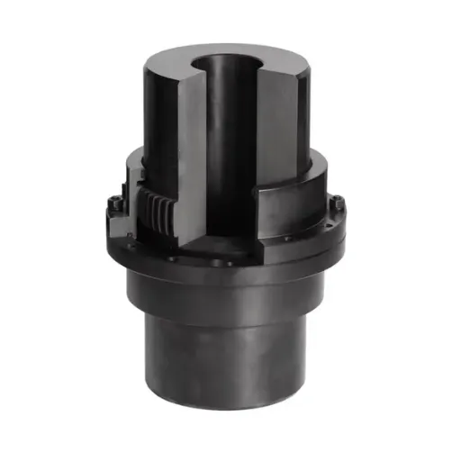
Gear couplings are more forgiving than rigid couplings, but they are not immune to poor installation. The teeth need correct mesh, the hubs need correct fits, and the assembly needs to be clean and balanced. When any of those conditions is wrong, the coupling wears faster, transmits vibration, and can damage bearings or gears.
What Happens When Installation Goes Wrong
A poorly installed coupling can cause:
Vibration that damages bearings and shortens motor life
Uneven tooth loading that leads to pitting and scoring
Loosened bolts that allow the hubs to shift on the shafts
Overheating from lack of lubricant or wrong lubricant
Repeated failures that are blamed on the coupling instead of the assembly process
Many of the failures described in gear coupling failure analysis guides actually start with installation errors. Getting the installation right is the cheapest form of reliability improvement.
Pre-Installation Preparation
A successful gear coupling installation procedure starts before the coupling touches the shaft. Preparation prevents the delays and mistakes that happen when technicians discover missing tools or incorrect parts halfway through the job.
Gather the Right Information
Before starting, collect the following:
The coupling drawing or catalog page with bore sizes, bolt sizes, and torque values
The shaft diameters and keyway dimensions for both driving and driven shafts
The alignment targets from the machine manufacturer
The correct lubricant type and quantity
The bolt torque sequence and final torque value
Lockout/tagout procedures for the machine
If the coupling is a custom replacement, confirm that the bore sizes and keyways match the shafts. At Hebei Suju, we mark every custom coupling with the drawing number and bore sizes so installation teams can verify the part before they start.
Inspect the Coupling and Components
Check the coupling for shipping damage, corrosion, or contamination. Inspect the teeth for nicks or rust. Verify that all bolts, nuts, washers, seals, and gaskets are present.
If the coupling was stored for a long time, the factory preservation oil may have dried out. Clean the parts and apply fresh preservative if installation will be delayed.
Inspect the Shafts
Measure the shaft diameters at the hub locations. Compare them to the coupling bore dimensions. Look for fretting corrosion, wear ridges, or previous damage that could prevent a proper fit.
If the shaft is damaged, repair it before installing the new coupling. A damaged shaft will damage the next coupling too.
Step 1: Mount the Hubs on the Shafts
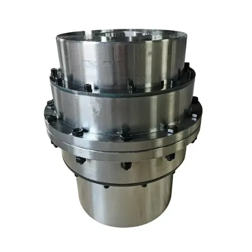
The hubs are the foundation of the installation. If the hubs are not mounted correctly, alignment and bolt torque cannot compensate for the error.
Clean the Bore and Shaft
Remove all rust, paint, old grease, and debris from the coupling bore and the shaft. Even a thin layer of contamination can reduce the interference fit and cause the hub to loosen. Use a fine abrasive cloth or approved cleaning solvent. Do not use a heavy grinder on the shaft because it can create out-of-roundness.
Check the Fit
For interference fits, the hub should require controlled heating or hydraulic pressure to mount. For clearance fits with keys, the hub should slide onto the shaft without forcing but should not have noticeable play. A loose hub fit is one of the most common causes of coupling failure.
Heat or Cool as Needed
For interference fits, heat the hub in an oven or induction heater to the temperature recommended by the manufacturer. Do not use an open flame because it can overheat local areas and change the material properties. For very large bores, cooling the shaft with dry ice or liquid nitrogen can make assembly easier.
Align the Keyway
Make sure the key sits properly in the shaft keyway before sliding the hub on. The key should not be forced. It should fit snugly along the bottom and sides without binding at the top. A key that is too tight can deform the hub bore.
Step 2: Align the Shafts in the Gear Coupling Installation Procedure
Shaft alignment is one of the most critical steps in the gear coupling installation procedure. Even though gear couplings tolerate misalignment, running near the limit increases wear and vibration.
Types of Misalignment to Correct
Angular misalignment: the shafts meet at an angle
Radial misalignment: the shaft centerlines are parallel but offset
Axial misalignment: the shafts are too close or too far apart axially
Measure all three types and compare them to the coupling manufacturer's allowable values. Remember that allowable values are often given for static cold alignment. The running alignment may change due to thermal growth, pipe strain, or foundation movement.
Use the Right Alignment Method
For most industrial drives, dial indicators or laser alignment tools are appropriate. Rough alignment with a straightedge is not accurate enough for gear couplings in critical service. Laser alignment is faster and leaves a documented record.
Align in the Hot Running Condition
When possible, calculate the expected thermal growth of the motor and gearbox housings and set the cold alignment so the coupling runs near zero misalignment at operating temperature. A common rule is to set the cold alignment with the motor shaft slightly lower than the driven shaft if the motor grows more thermally.
Step 3: Install the Sleeve and Connect the Hubs
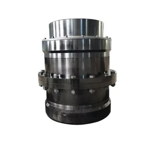
After the hubs are mounted and aligned, the sleeve can be installed between them. This step requires attention to cleanliness, bolt sequence, and sleeve orientation.
Clean the Teeth and Apply Lubricant
Before assembling the sleeve, coat the internal gear teeth with the correct lubricant. The lubricant should fill the tooth spaces without overflowing. Do not mix greases with different base oils or thickeners because they can separate or harden.
Check Sleeve Orientation
Some sleeves are symmetrical, but others have specific end markings or flange orientations. Verify the correct orientation against the drawing. Installing the sleeve backward can block lubrication passages or put the thrust shoulders in the wrong position.
Install Bolts in the Correct Sequence
Tighten the coupling bolts in a star or cross pattern, not clockwise around the flange. This prevents the sleeve from seating unevenly and introduces bolt preload uniformly. Use a calibrated torque wrench and tighten in two or three stages up to the final torque value.
Use the Correct Bolts
Always use the bolts supplied with the coupling or bolts of the same grade, length, and thread engagement. Substituting standard hardware store bolts is a common mistake that leads to loosening or breakage. If the coupling uses fitted bolts, ream the holes to match.
Step 4: Lubricate the Coupling
Lubrication is the lifeblood of a gear coupling. The teeth slide against each other during operation, and without proper lubricant film they will wear rapidly.
Choose the Correct Lubricant
Follow the coupling manufacturer's recommendation for lubricant type, grade, and quantity. Common choices include:
Lithium-based EP grease for general industrial applications
Polyurea grease for high-temperature applications
Mineral or synthetic oil for oil-lubricated couplings in high-speed or continuous service
The wrong lubricant can cause hardening, separation, or inadequate film strength.
Fill to the Correct Level
For grease-lubricated couplings, fill the space around the teeth to the level specified in the manual. Overfilling causes churning and overheating. Underfilling leaves teeth dry. For oil-lubricated couplings, set the oil level at the sight glass mark.
Protect Against Contamination
Make sure seals and gaskets are in good condition before closing the coupling. Contamination such as dust, metal chips, or water will accelerate wear. In harsh environments, consider labyrinth seals or additional shrouds.
Step 5: Check Runout and Verify the Gear Coupling Installation Procedure
After assembly, verify that the coupling runs true and that all fasteners are correct.
Measure Radial Runout
Place a dial indicator on the outside diameter of the coupling sleeve or hub. Rotate the shaft slowly and record the total indicated runout. Compare the reading to the manufacturer's limit. Runout above the limit usually means the hub is not seated squarely on the shaft or the sleeve is distorted.
Measure Axial Runout
Place a dial indicator on the face of the coupling flange. Rotate the shaft and check for face runout. Excessive face runout indicates angular misalignment or a bent sleeve.
Recheck Bolt Torque
After rotating the coupling by hand and after the first few hours of operation, recheck bolt torque. Bolts can settle slightly as the joint seats. Retorque to the specified value.
Step 6: Run the Initial Test
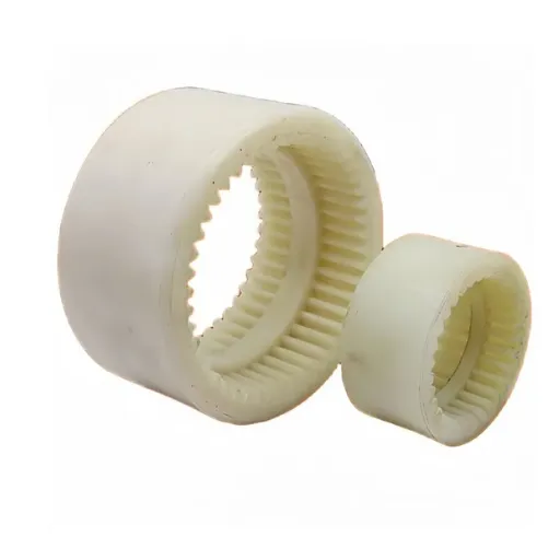
Before returning the machine to full production, run a careful test to confirm the installation.
Start Slowly
Run the machine at low speed first and listen for unusual noise or vibration. Check coupling temperature with an infrared thermometer. A hot coupling immediately after startup may indicate lack of lubricant or misalignment.
Monitor Vibration
Use a vibration analyzer if available. Compare the readings to baseline values from before the coupling change. A significant increase in vibration after installation means the alignment or balance needs rechecking.
Document the Results
Record alignment values, runout values, bolt torque, lubricant type, and vibration readings. This documentation becomes the baseline for future maintenance and failure analysis.
Common Installation Mistakes to Avoid
Even experienced teams make errors. Here are the mistakes that appear most often in the field.
| Mistake | Why It Damages the Coupling | How to Prevent It |
|---|---|---|
| Skipping shaft cleaning | Reduces hub fit, causes loosening | Clean bore and shaft thoroughly |
| Using wrong bolts | Lower strength, wrong preload | Use manufacturer-specified bolts |
| Incorrect torque sequence | Uneven flange loading | Tighten in star pattern, in stages |
| Over-greasing | Churning, heat, seal failure | Fill to specified level |
| Ignoring thermal growth | Hot misalignment | Align for running condition |
| Skipping runout check | Undetected assembly error | Measure radial and axial runout |
| Mixing lubricants | Chemical breakdown | Use one approved lubricant |
When to Call for Custom Support
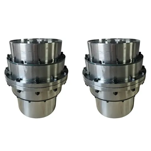
Some installations do not follow a standard procedure because the machine itself is non-standard. In those cases, a custom coupling and installation guidance from the manufacturer can save time and prevent repeat failures.
Situations That Need Custom Help
The shaft diameters do not match standard catalog bores
The space between shafts requires a special spacer sleeve
The operating temperature or environment needs special seals
The alignment targets are difficult to achieve with the existing foundation
You are replacing a legacy coupling and need to match the original dimensions
At Hebei Suju, we provide drawing-based custom couplings and installation guidance for non-standard applications. Send us your shaft dimensions and machine details, and our engineers will recommend the correct fit, lubrication, and alignment approach.
Installation Checklist
Use this checklist to make sure no step in the gear coupling installation procedure is missed.
Lock out and tag out the machine.
Verify coupling part number, bores, and keyways against shafts.
Clean shafts and coupling bores.
Mount hubs with correct fit and key alignment.
Align shafts within manufacturer limits, allowing for thermal growth.
Install sleeve with correct orientation and lubrication.
Tighten bolts in star pattern to specified torque.
Fill coupling with correct lubricant to correct level.
Check radial and axial runout.
Run test and record vibration and temperature.
Return machine to service and schedule first inspection.
Conclusion
A gear coupling installation procedure is not complicated, but it is unforgiving of shortcuts. Cleaning the shafts, mounting the hubs with the correct fit, aligning for the running condition, tightening bolts in sequence, and lubricating properly are the steps that separate a reliable installation from an early failure.
If your team is installing a replacement coupling or building a new drive, follow the checklist above and document every measurement. For non-standard shafts or difficult applications, a custom drum gear coupling from Hebei Suju can be manufactured to your exact dimensions and supplied with installation guidance.
Recently Posted
-
Jaw Coupling Spider Replacement: A Step-by-Step Maintenance Guide
July 28, 2026A maintenance technician at a packaging plant in Brazil noticed vibration on a motor-pump set during his morning rounds. The motor Read More
 -
Flexible Coupling for Motor Pump Sets: A Selection Guide
July 28, 2026A maintenance manager at a water treatment plant in Southeast Asia called us after replacing motor pump couplings three times in 1 Read More
 -
Flexible Shaft Coupling: Selection Guide for Industrial Drives
July 28, 2026When two rotating shafts are connected directly, even a small amount of misalignment can generate vibration, bearing load, and pre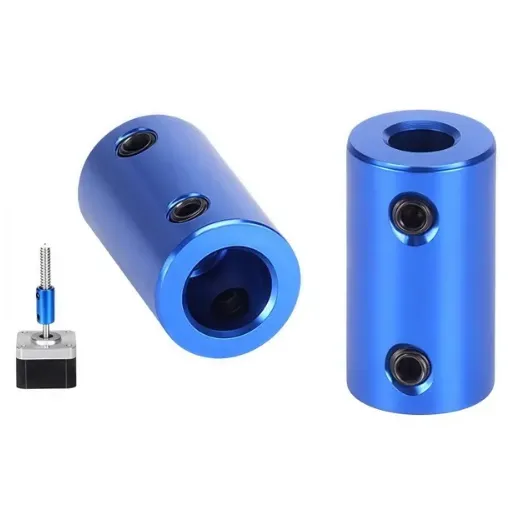 Read More
 -
Elastic Coupling: Vibration Control for Industrial Drives
July 28, 2026When a motor-pump set starts vibrating above acceptable limits, the first checks usually fall on bearing wear, impeller balance, o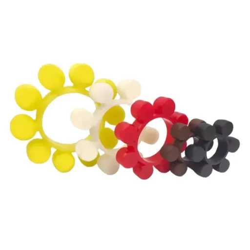 Read More

Contact Us

Recommended Products
-
 OEM Customizable Cardan Shaft Coupling Flexible Rigid Steel for Air Compressor Propeller Universal Construction Printing ShopsNegotiableMOQ: 2 Pieces
 -
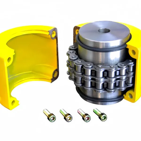
Kc Coulpling Roller Chain Coupling Set With Chain and Sprocket for General MachineryNegotiableMOQ: 1 Piece
-
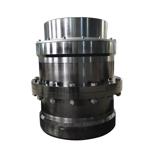
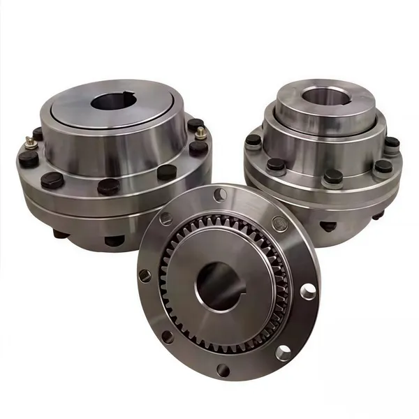
High Transmission Efficiency Drum Gear Coupling Easy Installation Gear Coupler For Heavy MachineryNegotiableMOQ: 10 Pieces
-
High-Torque Roller Chain Coupling Durable Steel Aluminium Construction Customizable Precision Engineering OEM Shaft CouplingsNegotiableMOQ: 2 Pieces
-
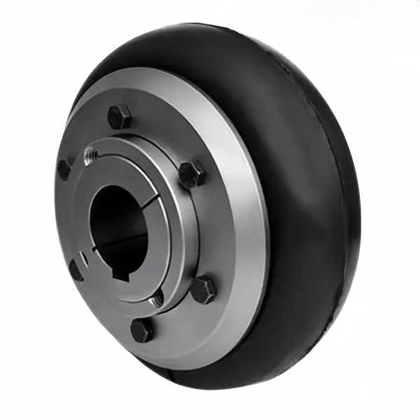
Customizable Rigid Iron Steel Aluminium Rubber Tyre Coupling OEM Support for Pumps Industrial Equipment Construction IndustriesNegotiableMOQ: 10 Pieces
-
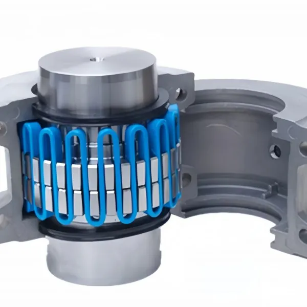
Jsb Flexible Grid Coupling With Metallic Elastic Element Factory Direct Spider Snake Spring CouplingNegotiableMOQ: 10 Pieces
-
High Torque JQ/JQW Type Clamp Coupling for Motor & Gearbox 45 Steel Jacketed Iron Disc Structure Flexible Rigid OEM SupportedNegotiableMOQ: 2 Pieces
-
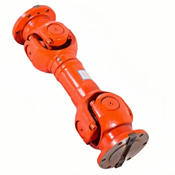
SWC Series Flange Universal Joint Coupling Hardened Cross Shaft Heavy Duty TransmissionNegotiableMOQ: 1 Piece
-
Heavy Duty Universal Coupling High Quality Universal Shaft for Machinery and EquipmentNegotiableMOQ: 1 Piece
-
OEM Customized Precision Cast Iron Zinc Aluminum Die Castings New Hydraulic Parts Fittings 1 Year WarrantyNegotiableMOQ: 100 Pieces
-
Yl Series Rigid Flange Coupling Power Transmission PartsNegotiableMOQ: 2 Pieces
-
Flange Coupling for Water Pump and Compressor Applications With Rubber Gasket SealNegotiableMOQ: 2 Pieces
-
Heavy-Duty Telescopic Welding Cardan Shaft for Universal UseNegotiableMOQ: 1 Piece
-
Flexible Universal Shaft Flange Coupling for Marine and Industrial Drive SystemsNegotiableMOQ: 10 Pieces
-
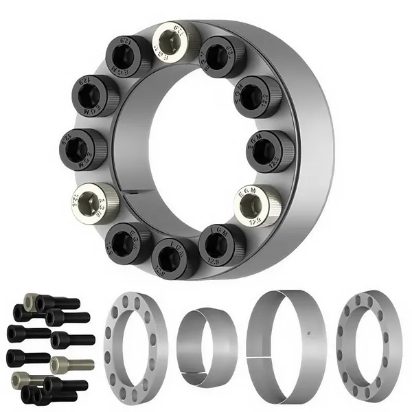
Durable Expansion Sleeve, Locking Assembly & Taper Lock Bushing for Robotic Arm JointsNegotiableMOQ: 1 Piece
-
High Quality Yl Type Rigid Flange Coupling Mechanical Transmission CouplingNegotiableMOQ: 2 Pieces
-
Stainless Steel Flexible Universal Joint Coupling for Motor Flange Gear Pump and Spline ShaftNegotiableMOQ: 1 Piece
-
Compact Drum Gear Coupling for Heavy Industrial Transmission High Torque CapacityNegotiableMOQ: 10 Pieces
-
Standard or Customized Jaw Beam (Helical) Flexible Coupling for General MachineryNegotiableMOQ: 10 Pieces
-
TL Series Elastic Pin Coupling Easy Replace Rubber Bush Coupling With Shaft Misalignment CompensationNegotiableMOQ: 10 Pieces