
 Business License
Gear Coupling Failure Analysis: How to Find the Real Root Cause
Mikhail pulled the inspection cover off the reversing roughing mill gearbox coupling on a Tuesday morning in Magnitogorsk and found teeth that looked like someone had attacked them with a grinder. The mill had run only 18 months since the last replacement. A sales rep from the original supplier blamed the material. Mikhail's maintenance foreman blamed the operators for too many cobbles.
The truth was simpler, and more expensive: the coupling had been sized for normal rolling torque but the drive was starting under full slab load, and the peak torque was almost double the catalog rating.
If you have ever stared at a failed gear coupling and wondered why it really broke, you are not alone. Gear coupling failure analysis is one of the most useful skills a maintenance engineer can develop, because the part that failed is often the symptom, not the disease. In this guide you will learn how to read the damage patterns on gear coupling teeth, hubs, and seals, what each pattern says about the operating condition, and how to prevent the same failure from repeating.
We will cover overload, misalignment, lubrication breakdown, fatigue, contamination, and installation errors. You will also see how to document a failure so your supplier can recommend a better replacement or a custom upgrade.
Why Gear Coupling Failure Analysis Matters
A gear coupling does not usually fail without warning. It leaves evidence on the tooth flanks, in the lubricant, and on the mating surfaces. The problem is that most maintenance teams replace the coupling and move on, so the root cause survives to destroy the next one. That is why a disciplined gear coupling failure analysis process pays for itself quickly.
The Cost of a Wrong Diagnosis
Replacing a coupling costs more than the part. It includes labor, crane time, lost production, and sometimes secondary damage to bearings or gears. If the new coupling is identical to the old one and the operating condition has not changed, the failure interval will be similar.
For example, a cement mill in central Mexico replaced a broken gear coupling three times in four years. Each time the supplier sent the same size. A proper gear coupling failure analysis showed the bore was slowly walking on the motor shaft because the interference fit had been reduced by fretting corrosion. Switching to a larger interference fit and adding a locking compound extended the next coupling life to more than seven years.
What a Good Analysis Includes
A useful gear coupling failure analysis answers four questions:
What part of the coupling failed first? Teeth, hub bore, bolts, seals, or sleeve?
What does the damage surface look like? Pitting, scoring, wear, cracking, or plastic deformation?
What was the operating condition before failure? Load, speed, temperature, lubrication, and alignment data.
What changed before the failure started? New motor, new load, new operators, or delayed maintenance?
If you can answer those four questions, you can usually identify the root cause and specify a coupling that will not repeat the failure. This structured approach is the core of practical gear coupling failure analysis.
Failure Mode 1: Overload and Peak Torque Damage
Overload failures happen when the torque transmitted through the coupling exceeds its capacity. Gear coupling failure analysis almost always starts here because the damage is visible and the cause feels obvious. The hard part is proving whether the overload was occasional or routine.
What Overload Damage Looks Like
The classic sign is plastic deformation at the tooth tips or roots. Teeth may appear rolled, smeared, or sheared off completely. In severe cases the hub bore will spin on the shaft and create fretting marks or a polished bore surface.
If only one side of the teeth is damaged, the overload may have happened during a single direction event such as a jam or a crash. If both sides show wear, the coupling has been running above its rated torque repeatedly.
Common Causes of Overload
Starting a motor under full load without a soft starter
Drive train jams caused by foreign material or seized bearings
Braking torques higher than the coupling rating
Undersizing the coupling because nominal torque was used without a service factor
Emergency reversing loads in cranes and rolling mills
Real-World Example: The Indonesian Paper Machine
A paper machine in Sumatra used a gear coupling between the dryer section gearbox and the driven roll. The coupling teeth showed polished flanks and small cracks at the roots after 14 months. The maintenance team assumed fatigue.
The actual cause was an oversized brake that stopped the section in three seconds instead of the designed eight seconds. The braking torque was 2.4 times the rated torque. A larger coupling with a higher peak torque rating and a slower brake ramp solved the problem.
Failure Mode 2: Misalignment and Its Signature
Gear couplings tolerate misalignment better than rigid couplings, but they do not tolerate it forever. Excessive angular, radial, or axial misalignment creates edge loading, uneven tooth wear, and premature failure.
Angular Misalignment
When the shafts meet at an angle, the coupling teeth load heavily on one end of the tooth face. The result is a wear pattern that is heavy on one side and almost clean on the other. The sleeve may also show axial thrust marks because the coupling tries to climb out of the misalignment.
Radial Misalignment
Parallel offset causes the teeth to load on the side closest to the offset. The wear pattern is offset to one side of the tooth face, and the sleeve bore may show oval wear.
Axial Misalignment
End float or thermal expansion beyond the coupling's allowable axial travel causes the teeth to bottom out. The damage appears as heavy wear at the tooth ends, chipped tips, or impact marks where the hubs hit the sleeve shoulders.
How to Verify Misalignment as the Cause
Measure the shafts after removing the coupling. Compare the readings to the coupling manufacturer's allowable values. Also check whether the allowable values were based on static cold alignment or on hot running conditions. A gearbox housing that grows thermally by 0.5 mm can turn an acceptable cold alignment into a severe hot misalignment.
Failure Mode 3: Lubrication Breakdown
A gear coupling depends on lubricant to separate the teeth, carry away heat, and flush wear particles. When lubrication fails, metal contacts metal, and failure accelerates rapidly.
Signs of Lubrication Failure
The most obvious sign is dry, discolored teeth with heavy adhesive wear. The lubricant may be black, thick, and full of metal particles. In extreme cases the teeth will show blue temper colors from overheating.
Why Lubrication Fails
Wrong lubricant grade for the operating temperature
Grease that has separated or hardened in storage
Oil level too low in oil-lubricated couplings
Seal failure allowing grease to leak out and contamination to enter
Extended maintenance intervals beyond the manufacturer's recommendation
High-speed operation that throws grease away from the tooth mesh
Grease vs Oil Lubrication
Grease-lubricated couplings are simpler but less effective at removing heat. They work well at moderate speed and load. Oil-lubricated couplings are better for high-speed or continuous-duty applications because oil circulates and cools. If a grease-lubricated coupling keeps failing from heat, converting to oil lubrication may be the right fix.
Failure Mode 4: Fatigue and Cyclic Loading
Fatigue failures occur after many load cycles, even when the peak load is within the coupling's rated capacity. The damage starts as small cracks at stress concentrations such as tooth roots, keyways, or bore corners. The cracks grow slowly, then suddenly cause a fracture.
What Fatigue Looks Like
Fatigue cracks usually show beach marks or progressive growth lines on the fracture surface. The final fracture area is rough and fibrous. On gear teeth, fatigue appears as pitting or spalling that starts at the pitch line and spreads.
Factors That Accelerate Fatigue
High cycle counts from continuous operation
Torsional vibration or torque ripple from the driven machine
Stress concentrations from poor tooth root geometry
Corrosion from moisture or chemicals reducing fatigue strength
Residual tensile stresses from heat treatment or machining
A Case from a German Steel Plant
A converter tilting drive in Duisburg suffered repeated hub fractures after about three years of service. The fractures all started at the keyway corner. Metallurgical analysis showed the keyway had been machined with a sharp corner radius instead of the specified relief.
Stress concentration at the corner initiated fatigue cracks. The solution was to specify a larger radius and a reduced keyway depth on replacement hubs.
Failure Mode 5: Contamination and Corrosion
Dust, water, and process chemicals are enemies of gear couplings. Contamination accelerates abrasive wear, and corrosion reduces the fatigue strength of the teeth and hubs.
Contamination Damage Patterns
Abrasive wear creates a dull, scratched surface across the tooth flanks. The wear rate increases over time as particles embed in the grease and act like grinding paste. The lubricant will feel gritty and may contain visible particles.
Corrosion Damage Patterns
Corrosion appears as reddish-brown staining, pitting, or general surface roughening. Pitting is especially dangerous because each pit acts as a stress riser and starts fatigue cracks.
How Contamination Gets In
Damaged or missing seals
Open-style couplings in dusty environments
Washdown procedures that force water into the coupling
Outdoor equipment exposed to rain and humidity
Process spills such as acids, alkalis, or salts
For contaminated environments, specify sealed couplings with improved lip or labyrinth seals. In extremely hostile environments, consider stainless steel or corrosion-resistant coatings.
Failure Mode 6: Installation and Assembly Errors
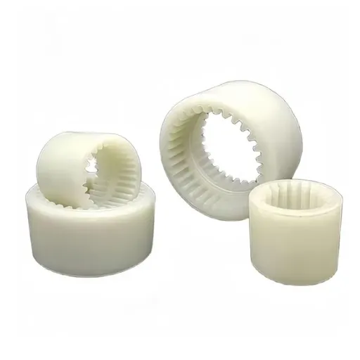
Even a correctly sized coupling can fail quickly if it is installed wrong. Installation errors are frustrating because they are easy to prevent but expensive to fix after failure.
Common Installation Mistakes
Hub fit too loose on the shaft, allowing bore spinning and fretting
Hub fit too tight, causing stress cracking in the hub
Bolts tightened unevenly, creating hub runout and vibration
Keys too tight or too loose in the keyway
Missing or wrong shims during alignment
Forcing the coupling into alignment by bending pipework
Not checking runout after assembly
The Importance of Runout Checks
After installation, measure radial and axial runout on the coupling hubs. A few tenths of a millimeter of runout can create vibration and misalignment loading that leads to early failure. Runout checks are especially important on motors and gearboxes that have been refurbished.
How to Document a Failed Coupling for Analysis
Good documentation makes gear coupling failure analysis faster and more accurate. Before you throw the coupling in the scrap bin, record the following.
Photograph Everything
Take clear photos of the overall coupling, the failed area, and close-ups of the damage surfaces. Include a scale or ruler in the photo for size reference. Photograph both mating parts because the damage on the hub may differ from the damage on the sleeve.
Collect Samples
Save a section of the failed tooth or hub if metallurgical analysis is needed. Keep a sample of the lubricant and any contamination. Place samples in clean bags and label them with the date, machine name, and operating hours.
Record Operating Data
Write down motor power, speed, load profile, starting method, brake details, and operating temperature. Note any recent changes such as new motors, new loads, or maintenance work. If you have vibration data or alignment records, include those too.
Measure the Coupling
Record the actual bore diameters, keyway sizes, overall length, and tooth dimensions. Compare these to the original drawing if you have it. Sometimes a previous repair shop modified the coupling in ways that weakened it.
How to Prevent Repeat Failures
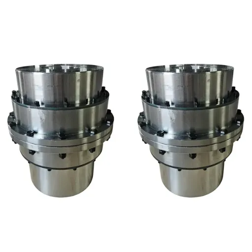
Once you know the root cause, you can specify a better solution. The table below is a practical gear coupling failure analysis tool that matches common failure modes to immediate fixes and long-term prevention strategies.
| Failure Mode | Immediate Fix | Long-Term Prevention |
|---|---|---|
| Overload | Check service factor and peak torque | Size coupling for peak loads; add soft starter or torque limiter |
| Misalignment | Realign shafts; check hot alignment | Improve foundation rigidity; schedule alignment checks |
| Lubrication failure | Clean and relubricate; replace seals | Use correct lubricant; shorten intervals; consider oil lube |
| Fatigue | Inspect for cracks during shutdowns | Improve tooth root geometry; reduce stress concentrations |
| Contamination | Replace seals; clean housing | Specify sealed coupling; protect from washdown |
| Installation error | Reinstall with correct fits and torque | Train maintenance team; use runout checks |
For critical drives, consider keeping a spare coupling on site. The cost of a spare is usually small compared to the cost of unplanned downtime.
When to Order a Custom Replacement
Sometimes a standard catalog coupling cannot survive the actual operating condition. In those cases, a custom gear coupling designed for the real load profile is the most cost-effective choice.
Situations That Warrant Custom Design
The standard coupling is at the top of its torque range with no safety margin
Misalignment is unavoidable due to machine design
The environment requires special seals or materials
The drive has high torsional vibration that standard couplings cannot absorb
You need to match a legacy coupling that is no longer available
At Hebei Suju, we review failed couplings and operating data to recommend material, heat treatment, tooth geometry, and fit changes that solve the root cause. You can send us your drawing or a sample for a failure review and quotation.
A Practical Failure Analysis Checklist
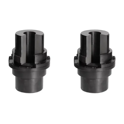
Use this checklist the next time a gear coupling fails on your plant.
Stop the machine and lock it out safely.
Photograph the coupling in place before removal.
Remove the coupling and mark the shaft positions.
Inspect teeth, bores, bolts, keys, and seals for damage patterns.
Measure shaft alignment and coupling runout.
Collect lubricant and wear debris samples.
Record operating hours, loads, speeds, and recent changes.
Compare the coupling size to the actual drive requirements.
Consult the supplier with photos and data.
Specify a replacement that addresses the root cause, not just the symptom.
Conclusion
Gear coupling failure analysis is not just about finding what broke. It is about finding why it broke so you can stop it from happening again. The damage pattern on the teeth, bores, and seals tells a story about overload, misalignment, lubrication, fatigue, contamination, or installation error. Learning to read that story saves money, reduces downtime, and improves reliability.
If you are dealing with a repeated coupling failure, start with the checklist above and gather the operating data before ordering a replacement. For critical applications, a custom drum gear coupling sized for the real load condition may be the only lasting fix.
Recently Posted
-
Jaw Coupling Spider Replacement: A Step-by-Step Maintenance Guide
July 28, 2026A maintenance technician at a packaging plant in Brazil noticed vibration on a motor-pump set during his morning rounds. The motor Read More
 -
Flexible Coupling for Motor Pump Sets: A Selection Guide
July 28, 2026A maintenance manager at a water treatment plant in Southeast Asia called us after replacing motor pump couplings three times in 1 Read More
 -
Flexible Shaft Coupling: Selection Guide for Industrial Drives
July 28, 2026When two rotating shafts are connected directly, even a small amount of misalignment can generate vibration, bearing load, and pre Read More
 -
Elastic Coupling: Vibration Control for Industrial Drives
July 28, 2026When a motor-pump set starts vibrating above acceptable limits, the first checks usually fall on bearing wear, impeller balance, o Read More

Contact Us

Recommended Products
-
 OEM Customizable Cardan Shaft Coupling Flexible Rigid Steel for Air Compressor Propeller Universal Construction Printing ShopsNegotiableMOQ: 2 Pieces
 -
Kc Coulpling Roller Chain Coupling Set With Chain and Sprocket for General MachineryNegotiableMOQ: 1 Piece
-
High Transmission Efficiency Drum Gear Coupling Easy Installation Gear Coupler For Heavy MachineryNegotiableMOQ: 10 Pieces
-
High-Torque Roller Chain Coupling Durable Steel Aluminium Construction Customizable Precision Engineering OEM Shaft CouplingsNegotiableMOQ: 2 Pieces
-
Customizable Rigid Iron Steel Aluminium Rubber Tyre Coupling OEM Support for Pumps Industrial Equipment Construction IndustriesNegotiableMOQ: 10 Pieces
-
Jsb Flexible Grid Coupling With Metallic Elastic Element Factory Direct Spider Snake Spring CouplingNegotiableMOQ: 10 Pieces
-
High Torque JQ/JQW Type Clamp Coupling for Motor & Gearbox 45 Steel Jacketed Iron Disc Structure Flexible Rigid OEM SupportedNegotiableMOQ: 2 Pieces
-
SWC Series Flange Universal Joint Coupling Hardened Cross Shaft Heavy Duty TransmissionNegotiableMOQ: 1 Piece
-
Heavy Duty Universal Coupling High Quality Universal Shaft for Machinery and EquipmentNegotiableMOQ: 1 Piece
-
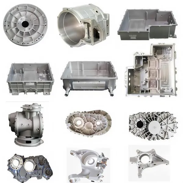
OEM Customized Precision Cast Iron Zinc Aluminum Die Castings New Hydraulic Parts Fittings 1 Year WarrantyNegotiableMOQ: 100 Pieces
-
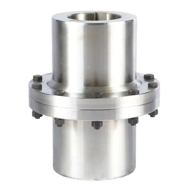
Yl Series Rigid Flange Coupling Power Transmission PartsNegotiableMOQ: 2 Pieces
-
Flange Coupling for Water Pump and Compressor Applications With Rubber Gasket SealNegotiableMOQ: 2 Pieces
-
Heavy-Duty Telescopic Welding Cardan Shaft for Universal UseNegotiableMOQ: 1 Piece
-
Flexible Universal Shaft Flange Coupling for Marine and Industrial Drive SystemsNegotiableMOQ: 10 Pieces
-
Durable Expansion Sleeve, Locking Assembly & Taper Lock Bushing for Robotic Arm JointsNegotiableMOQ: 1 Piece
-
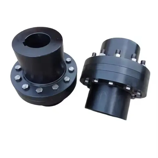
High Quality Yl Type Rigid Flange Coupling Mechanical Transmission CouplingNegotiableMOQ: 2 Pieces
-
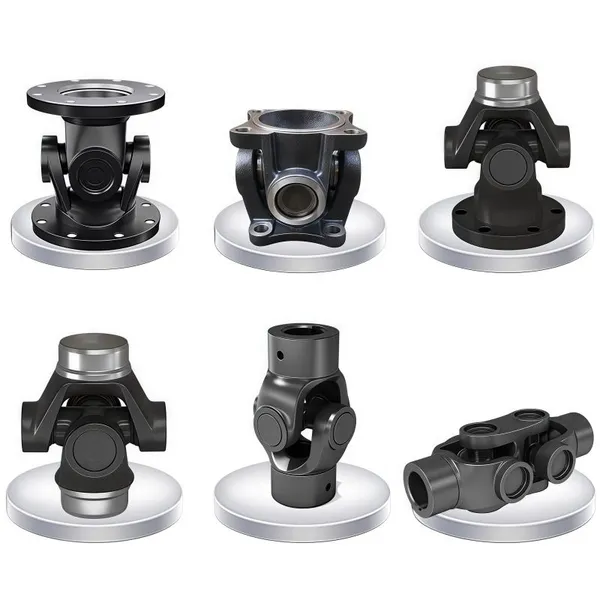
Stainless Steel Flexible Universal Joint Coupling for Motor Flange Gear Pump and Spline ShaftNegotiableMOQ: 1 Piece
-
Compact Drum Gear Coupling for Heavy Industrial Transmission High Torque CapacityNegotiableMOQ: 10 Pieces
-
Standard or Customized Jaw Beam (Helical) Flexible Coupling for General MachineryNegotiableMOQ: 10 Pieces
-
TL Series Elastic Pin Coupling Easy Replace Rubber Bush Coupling With Shaft Misalignment CompensationNegotiableMOQ: 10 Pieces