
 Business License
Diaphragm Coupling Applications: Where High Speed and Precision Matter
A European compressor OEM shipped a new hydrogen recycle compressor to a refinery in early 2025. Within six months, vibration alarms were triggering weekly. Bearing temperatures climbed. The culprit was not the motor, the impeller, or the foundation. It was the coupling between the motor and gearbox, chosen for cost rather than speed capability.
That story repeats in plants around the world. Engineers specify motors, bearings, and seals with care, then treat the coupling as an afterthought. In high-speed and precision machinery, that decision is expensive. This article explores the most important diaphragm coupling applications and explains why this zero backlash coupling is often the right choice for critical rotating equipment.
You will learn where diaphragm couplings outperform other flexible coupling types, what each application demands, and how to match the coupling to your operating conditions. Whether you design turbo machinery or maintain existing equipment, this guide will help you make a reliable choice.
At Hebei Suju, we supply diaphragm couplings for compressors, turbines, pumps, test stands, and automation equipment. Our engineering team also manufactures custom designs from your drawing or sample.
What Makes a Diaphragm Coupling Different
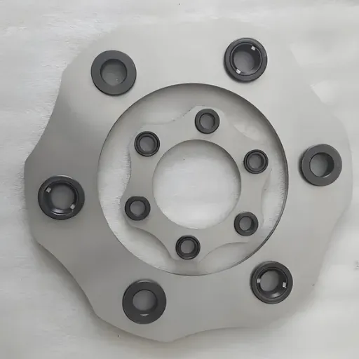
A diaphragm coupling transmits torque through thin metal discs, or diaphragms, arranged in a pack between two hubs. The discs flex to accommodate angular, axial, and limited radial misalignment while remaining torsionally stiff. There is no rubber element, no lubrication, and no backlash.
This construction gives the diaphragm coupling three advantages that define its best applications:
Zero backlash. The metal discs are rigid in rotation, so there is no lost motion between driving and driven shafts.
High speed capability. Properly balanced units operate reliably above 10,000 RPM and can exceed 30,000 RPM in precision designs.
Wide environmental tolerance. Stainless steel diaphragms resist high temperatures, chemicals, and contamination better than elastomeric elements.
These characteristics make the diaphragm coupling a precision coupling, not a general-purpose flexible coupling. It is the right tool when rotational accuracy, balance, and reliability matter more than large misalignment capacity.
For a broader comparison of flexible shaft connectors, see our guide to flexible coupling types.
Turbo Compressors and High-Speed Blowers
Centrifugal and axial compressors operate at speeds where small imbalances create large forces. A coupling at 12,000 RPM with poor balance can generate vibration that damages bearings, seals, and the compressor rotor itself. Diaphragm couplings solve this problem by providing a torsionally stiff, lightweight connection that can be precision balanced.
In turbo compressors, the coupling connects the motor or gearbox to the compressor shaft. The application demands:
High torque transmission at high speed
Minimal unbalance to protect bearings
No lubricant leakage into the process gas
Tolerance for thermal growth and casing expansion
A double diaphragm or spacer diaphragm coupling is usually specified because the two disc packs handle misalignment better than a single diaphragm design. Spacer designs also allow the coupling to be removed without moving the connected machines, which simplifies compressor maintenance.
Refineries and petrochemical plants often use API 671 couplings for critical turbo machinery. These special-purpose couplings meet strict standards for balance, material, and documentation because compressor failures can shut down entire process units.
Gas and Steam Turbines
Turbine-driven generators, pumps, and compressors present a difficult combination of high speed, high temperature, and continuous operation. A gas turbine coupling may see speeds above 10,000 RPM and temperatures that would destroy an elastomeric element. Steam turbine couplings must tolerate thermal expansion between the turbine casing and the driven equipment.
Diaphragm couplings fit these conditions because the metal disc pack handles both torque and temperature. They are used between:
Gas turbines and generators in power plants
Steam turbines and feedwater pumps
Turbines and compressors in process plants
Small turbine packages for offshore and distributed power
The long service life and minimal maintenance of diaphragm couplings are especially valuable in turbine applications because downtime is expensive and access is often limited. Many turbine couplings are also designed with a spacer to permit axial removal during overhaul.
When specifying a turbine coupling, engineers must consider torsional natural frequencies, thermal growth, and emergency torque events such as generator short circuits. The coupling must survive these events without failure.
High-Speed Pumps and API Equipment
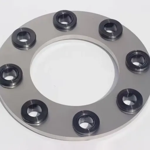
API 610 centrifugal pumps and API 671 turbo expanders are common diaphragm coupling applications. These pumps handle hydrocarbons, chemicals, and boiler feedwater where reliability is critical. The coupling must transmit torque smoothly, maintain balance, and avoid introducing contaminants into the pumped fluid.
Diaphragm couplings are preferred over gear couplings in many pump services because they require no lubrication. There is no grease or oil to leak into the process stream, no lubrication schedule to manage, and no wearing teeth to inspect.
Common pump applications include:
Boiler feedwater pumps in power plants
Pipeline pumps in oil and gas transport
Chemical process pumps
Cryogenic and refrigerant pumps
Cooling water pumps in nuclear and conventional power stations
In these services, the diaphragm coupling for pumps must be selected for torque, speed, and the expected misalignment caused by pipe strain and thermal expansion. A spacer design is often chosen to allow pump seal maintenance without disturbing the motor.
Test Stands and Dynamometers
Engine test cells, transmission dynamometers, and motor test stands need accurate torque and speed measurement. Any backlash or torsional flexibility in the coupling introduces hysteresis into the measurement. That makes the test data less repeatable and harder to interpret.
A zero backlash coupling is essential in these applications. The diaphragm coupling transmits torque directly from the driving motor to the dynamometer or from the test engine to the load brake. Because the metal discs do not compress or slip, sensors measure true shaft torque without lost motion.
An automotive test cell engineer named Li Wei needed to connect a 250 kW electric motor to a high-speed gearbox for durability testing. The original gear coupling required monthly lubrication and produced small torsional oscillations that affected measurement accuracy. After replacing it with a double diaphragm coupling, the test cell eliminated lubrication stops and improved torque signal repeatability by 15%.
Test stand couplings are often custom designs because the shaft spacing, bore sizes, and balance grades do not match standard catalog products. Hebei Suju manufactures custom couplings for test equipment builders who need precise, repeatable connections.
Machine Tools and Servo Drives
CNC machine tools, robots, and automation equipment use servo motors to control position with high accuracy. The coupling between the servo motor and ball screw or gearbox must preserve that accuracy. Even small amounts of backlash create positioning errors and surface finish problems.
Diaphragm couplings are the preferred precision coupling for many servo applications because they provide:
Zero backlash for accurate positioning
High torsional stiffness for fast response
Compact size for crowded machine enclosures
No maintenance between machine service intervals
Common automation applications include:
CNC lathes and machining centers
Semiconductor manufacturing equipment
Packaging and labeling machines
Robotic arms and pick-and-place systems
Printing and converting machinery
In these applications, the coupling is usually a single or double diaphragm design with low inertia. Engineers must also check the coupling's rated torque against the peak torque during rapid acceleration and reversing moves.
Diaphragm Coupling Applications by Industry
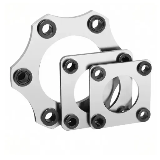
The table below summarizes where diaphragm couplings are most commonly used and why they fit.
| Industry | Typical Equipment | Why Diaphragm Couplings Fit |
|---|---|---|
| Oil and gas | Turbo compressors, pipeline pumps | High speed, no lubricant leakage |
| Power generation | Gas turbines, steam turbines, feedwater pumps | High temperature, continuous duty |
| Petrochemical | Process pumps, expanders, turbo blowers | Corrosion resistance, API standards |
| Automotive | Test stands, dynamometers | Zero backlash, accurate torque measurement |
| Machine building | CNC machines, servo drives, robots | Precision, compact size, no maintenance |
| Aerospace | Auxiliary drives, test equipment | Light weight, high speed, balance |
| Marine | Pump drives, auxiliary turbines | Compact design, saltwater resistance |
This table is not exhaustive. Any rotating system that needs accurate torque transmission at high speed is a potential diaphragm coupling application.
Selecting a Diaphragm Coupling for Your Application
Choosing the right diaphragm coupling requires more than matching a catalog part number. Engineers should evaluate the application as a system. The five factors below determine whether the coupling will deliver long, reliable service.
1. Torque and Speed
Calculate the nominal torque from motor power and operating speed. Then apply a service factor based on the duty cycle. For smooth, continuous loads, the service factor may be 1.25 to 1.5. For pulsating or reversing loads, use 1.5 to 2.5.
High-speed applications require careful attention to balance. Specify dynamic balancing to ISO 1940 or AGMA 9000-C14 requirements when speeds exceed 3,000 RPM. The cost of balancing is small compared to the cost of vibration damage.
2. Misalignment
Diaphragm couplings tolerate less misalignment than gear or tyre couplings. Measure angular, radial, and axial misalignment at operating temperature, not just at cold alignment. Thermal growth, pipe strain, and foundation settlement all change the shaft positions.
A good practice is to keep actual misalignment below 50% of the manufacturer's rated value. This margin reduces cyclic stress in the diaphragm pack and extends fatigue life.
3. Environment
Consider temperature range, chemical exposure, and contamination. Stainless steel diaphragms handle most industrial environments, but extreme conditions may require special alloys such as Inconel or titanium. Offshore and chemical plant applications often need corrosion-resistant materials or coatings.
4. Torsional Stiffness
For servo and precision applications, verify that the coupling's torsional stiffness meets the control system requirements. A coupling that is too flexible allows resonant oscillations. A coupling that is too stiff transmits shock loads to bearings.
5. Standards and Documentation
Critical applications may require compliance with API, AGMA, or DIN standards. Request material certificates, inspection reports, and balance certificates when these are required for your project documentation.
For a deeper look at coupling selection in heavy-duty environments, read our guide on how to select a gear coupling for heavy machinery.
When to Consider a Custom Diaphragm Coupling
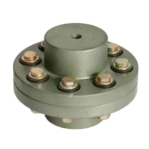
Standard catalog couplings cover many applications, but specialized equipment often needs a custom design. Consider a custom diaphragm coupling when:
Shaft bores or keyways are non-standard.
Spacer length does not match catalog dimensions.
Speed or torque falls outside standard ranges.
The environment requires special materials such as Inconel or titanium.
You need to replace a legacy coupling that is no longer manufactured.
A petrochemical plant in the Middle East needed to replace a diaphragm coupling on a critical ethylene compressor. The original manufacturer had discontinued the model, and the shaft spacing was unique. Hebei Suju reverse-engineered the coupling from a worn sample, produced a custom stainless steel diaphragm pack, and delivered the replacement within the plant's scheduled turnaround window.
If you have a non-standard requirement, send us your drawing or sample for a free engineering review.
Installation Tips for Diaphragm Coupling Applications
Even the best coupling will fail early if it is installed incorrectly. Follow these guidelines to protect your investment.
Align shafts within rated limits. Use laser alignment tools and check alignment at operating temperature.
Torque bolts evenly. Uneven tightening creates hub runout and imbalance.
Support overhung loads. Do not allow side loads from connected equipment to act on the diaphragm pack.
Protect during handling. The thin metal discs can be damaged by impact or improper storage.
Inspect on schedule. Check for cracks, loose bolts, and changes in vibration during planned shutdowns.
At Hebei Suju, our quality control process verifies dimensions, hardness, and balance before shipment. We can provide inspection reports and material certificates on request.
Conclusion
Diaphragm coupling applications are defined by three needs: high speed, precision, and reliability. From turbo compressors and gas turbines to test stands and servo drives, these couplings deliver zero backlash power transmission without lubrication or frequent maintenance.
Key takeaways:
Diaphragm couplings use metal discs to transmit torque and absorb misalignment.
They excel in high-speed rotating equipment such as compressors, turbines, and pumps.
Zero backlash makes them ideal for test stands, dynamometers, and servo drives.
Proper alignment and balance are critical for long service life.
Custom designs solve non-standard bore, spacing, and material requirements.
If you are specifying a new high-speed drive or replacing a coupling in critical equipment, Hebei Suju can help. Explore our flexible coupling range or request a quotation for your diaphragm coupling application.
Recently Posted
-
Jaw Coupling Spider Replacement: A Step-by-Step Maintenance Guide
July 28, 2026A maintenance technician at a packaging plant in Brazil noticed vibration on a motor-pump set during his morning rounds. The motor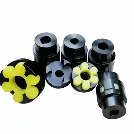 Read More
 -
Flexible Coupling for Motor Pump Sets: A Selection Guide
July 28, 2026A maintenance manager at a water treatment plant in Southeast Asia called us after replacing motor pump couplings three times in 1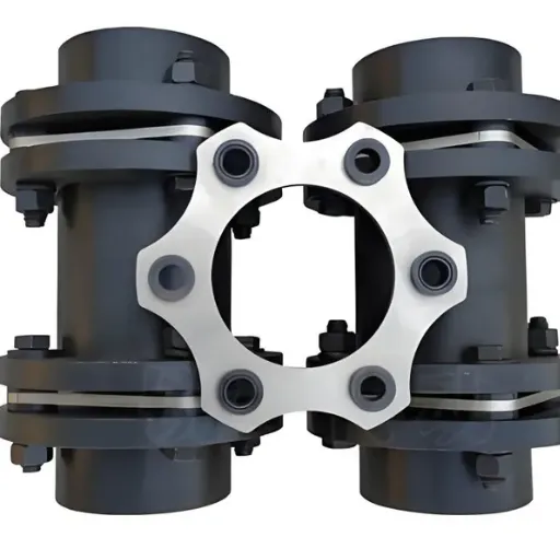 Read More
 -
Flexible Shaft Coupling: Selection Guide for Industrial Drives
July 28, 2026When two rotating shafts are connected directly, even a small amount of misalignment can generate vibration, bearing load, and pre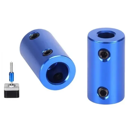 Read More
 -
Elastic Coupling: Vibration Control for Industrial Drives
July 28, 2026When a motor-pump set starts vibrating above acceptable limits, the first checks usually fall on bearing wear, impeller balance, o Read More

Contact Us

Recommended Products
-
 OEM Customizable Cardan Shaft Coupling Flexible Rigid Steel for Air Compressor Propeller Universal Construction Printing ShopsNegotiableMOQ: 2 Pieces
 -
Kc Coulpling Roller Chain Coupling Set With Chain and Sprocket for General MachineryNegotiableMOQ: 1 Piece
-
High Transmission Efficiency Drum Gear Coupling Easy Installation Gear Coupler For Heavy MachineryNegotiableMOQ: 10 Pieces
-
High-Torque Roller Chain Coupling Durable Steel Aluminium Construction Customizable Precision Engineering OEM Shaft CouplingsNegotiableMOQ: 2 Pieces
-
Customizable Rigid Iron Steel Aluminium Rubber Tyre Coupling OEM Support for Pumps Industrial Equipment Construction IndustriesNegotiableMOQ: 10 Pieces
-
Jsb Flexible Grid Coupling With Metallic Elastic Element Factory Direct Spider Snake Spring CouplingNegotiableMOQ: 10 Pieces
-
High Torque JQ/JQW Type Clamp Coupling for Motor & Gearbox 45 Steel Jacketed Iron Disc Structure Flexible Rigid OEM SupportedNegotiableMOQ: 2 Pieces
-
SWC Series Flange Universal Joint Coupling Hardened Cross Shaft Heavy Duty TransmissionNegotiableMOQ: 1 Piece
-
Heavy Duty Universal Coupling High Quality Universal Shaft for Machinery and EquipmentNegotiableMOQ: 1 Piece
-
OEM Customized Precision Cast Iron Zinc Aluminum Die Castings New Hydraulic Parts Fittings 1 Year WarrantyNegotiableMOQ: 100 Pieces
-
Yl Series Rigid Flange Coupling Power Transmission PartsNegotiableMOQ: 2 Pieces
-
Flange Coupling for Water Pump and Compressor Applications With Rubber Gasket SealNegotiableMOQ: 2 Pieces
-
Heavy-Duty Telescopic Welding Cardan Shaft for Universal UseNegotiableMOQ: 1 Piece
-
Flexible Universal Shaft Flange Coupling for Marine and Industrial Drive SystemsNegotiableMOQ: 10 Pieces
-
Durable Expansion Sleeve, Locking Assembly & Taper Lock Bushing for Robotic Arm JointsNegotiableMOQ: 1 Piece
-
High Quality Yl Type Rigid Flange Coupling Mechanical Transmission CouplingNegotiableMOQ: 2 Pieces
-
Stainless Steel Flexible Universal Joint Coupling for Motor Flange Gear Pump and Spline ShaftNegotiableMOQ: 1 Piece
-
Compact Drum Gear Coupling for Heavy Industrial Transmission High Torque CapacityNegotiableMOQ: 10 Pieces
-
Standard or Customized Jaw Beam (Helical) Flexible Coupling for General MachineryNegotiableMOQ: 10 Pieces
-
TL Series Elastic Pin Coupling Easy Replace Rubber Bush Coupling With Shaft Misalignment CompensationNegotiableMOQ: 10 Pieces