
 Business License
Gear Coupling for Rolling Mill Drives: A Selection Guide
In March 2026, Nguyen, a maintenance manager at a Vietnamese wire rod mill outside Hai Phong, spent three weeks chasing a vibration that kept tripping the finishing block. The motor, bearings, and foundation all checked out. The problem turned out to be the gear coupling between the motor and the pinion gearbox: after a repair, it had been rebalanced to G16 grade, but at 5,500 RPM the block needed G6.3. A pair of properly balanced couplings ended the trips in one weekend.
Selecting a gear coupling for rolling mill duty is a different discipline from general coupling selection. If you are responsible for a hot strip, cold rolling, bar, wire rod, or plate mill, you already know that the drive train decides how much steel the line rolls and how good the surface looks.
This guide explains where gear couplings sit in the rolling mill drive train, how each mill type changes the requirements, and how to size a gear coupling for rolling mill service with the right torque, balance, and lubrication choices. As a manufacturer supplying couplings and cardan shafts to rolling lines worldwide, Hebei Suju works with these drives daily, and this guide reflects that experience.
The Rolling Mill Drive Train: Where Gear Couplings Sit
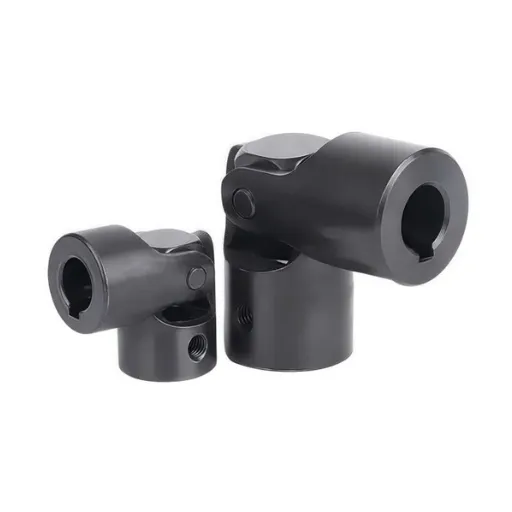
A rolling mill main drive looks simple on a single-line diagram: motor, coupling, gearbox, spindle, rolls. Each element creates a different demand on the coupling, and confusing the positions is the root of many selection errors.
The Motor-to-Gearbox Connection
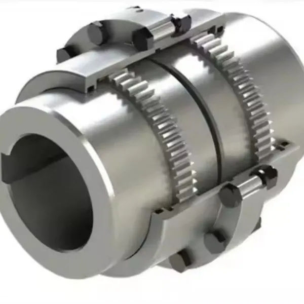
The motor coupling connects the main motor to the pinion stand or reducer. It runs at motor speed, transmits full drive torque, and absorbs the bite shock transmitted back through the gear teeth. This is the classic position for a drum gear coupling, because it combines high torque capacity with compensation for angular, radial, and axial misalignment.
On reversing roughing and plate mills, this coupling also sees every pass reversal. On tandem cold mills, it runs continuously at high steady torque, where smoothness matters more than shock capacity.
The Spindle Position: Why Cardan Shafts Dominate
Between the gearbox output and the work rolls sits the mill spindle. On hot mills, the spindle must accommodate roll gap adjustment, roll changes, and large angle variations, so a cardan shaft usually owns this position. Roughing and plate mill spindles commonly transmit more than 100,000 N·m, and universal-joint shafts handle the angular movement better than any gear coupling.
Some mills do run gear-type spindle couplings, especially older designs and heavy plate mills with limited gap adjustment. These couplings work in grease or oil baths and demand the highest material quality in the entire drive train.
Auxiliary and Coiler Drives
Beyond the main line, gear couplings drive coilers and uncoilers, pinch rolls, levelers, shears, roller tables, and cooling beds. GIICL drum gear couplings cover most of these positions.
This guide focuses on the rolling line itself. For plant-wide coupling selection that also covers mill cranes, runout tables, and descaling systems, see our gear coupling for steel mill guide.
How the Mill Type Changes Coupling Requirements
The words "rolling mill" cover machines with very different coupling demands. A wire rod finishing block at 5,500 RPM and a reversing plate mill at low speed with severe shock are opposite ends of the selection problem.
| Mill Type | Duty Character | Coupling Priorities |
|---|---|---|
| Hot strip mill | Bite shock, heat, continuous campaign | Shock capacity, sealed lubrication, thermal misalignment |
| Cold tandem / reversing mill | High steady torque, vibration-sensitive | Low backlash, torsional smoothness, balance grade |
| Plate mill (reversing) | Severe reversing shock, very high torque | Maximum service factor, peak torque margin |
| Bar mill | Frequent starts, multi-stand layout | Service factor, fast roll-change access |
| Wire rod mill | Very high finishing speeds | Dynamic balancing, precision bores |
| Blooming / section mill | Reversing, heavy shock | Shock capacity, robust teeth |
Hot strip and reversing mills punish couplings with bite impact every pass. Heat from the mill line adds thermal growth that shifts alignment between cold startup and rolling temperature.
Cold mills live and die on torsional behavior. Chatter marks on strip are sometimes blamed on the mill stand when the root cause is a worn coupling whose backlash lets the drive line oscillate.
Wire rod finishing blocks spin fast enough that balance grade becomes a first-order specification, as Nguyen's mill discovered. The GIICL drum gear coupling specifications guide covers the rating tables most bar, section, and auxiliary drives need.
The right gear coupling for rolling mill duty matches the mill type first and the torque number second. A coupling that survives a reversing plate mill may be the wrong choice for a cold tandem mill, even at the same rated torque.
How to Size a Gear Coupling for Rolling Mill Duty
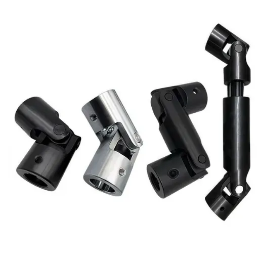
Sizing a gear coupling for rolling mill duty starts from rolling torque, not motor nameplate. Five checks, in the order that prevents the most failures.
1. Calculate Rolling Torque, Not Just Motor Torque
Rolling torque comes from the roll separating force acting on the lever arm between the bite line and the roll centerline. It divides between the top and bottom spindles, and the coupling upstream of the gearbox carries the sum.
Start from the mill designer's rolling load data or from measured motor current during rolling, then work back to torque. Nameplate power alone underestimates what the coupling actually transmits during a heavy reduction pass.
2. Apply the Service Factor and Check Bite Peak
Steel rolling carries some of the highest service factors in industry because of bite impact and reversing duty.
| Drive Position or Mill Type | Suggested Service Factor |
|---|---|
| Reversing roughing / plate main drive | 2.5-3.0 |
| Hot strip finishing main drive | 2.0-2.5 |
| Cold tandem mill main drive | 1.75-2.25 |
| Bar and section mill stands | 2.0-2.5 |
| Wire rod finishing block | 1.5-1.75, plus balance grade |
| Coilers, levelers, pinch rolls | 1.75-2.0 |
Multiply design torque by the service factor, then verify peak torque. Bite impact on hot mills and emergency stops can spike two to three times nominal, and the coupling's peak rating must cover the highest credible spike. Application factors from the American Gear Manufacturers Association and manufacturer catalogs provide the reference values.
3. Check Torsional Behavior and Backlash on Cold Mills
A gear coupling has inherent backlash, which grows as the teeth wear. On hot mills this is harmless within limits. On cold tandem mills producing automotive or appliance strip, excessive backlash can excite torsional vibration that prints chatter marks on the strip.
Specify new couplings with minimum practical backlash, and trend the measurement at every planned stop. When backlash roughly doubles from the as-built value, plan the replacement before surface quality forces the issue.
Elena, a drive engineer at a Spanish cold rolling mill, traced a recurring chatter pattern to a main drive coupling whose backlash had grown from 0.4 mm to 1.8 mm over four years. The mill had changed work rolls, ground backup rolls, and retuned the drive controller, all without removing the marks. A replacement coupling, specified with tight backlash and inspected on arrival, cleared the pattern in the next campaign.
4. Match the Balance Grade to the Speed
Most rolling mill main drives run below 1,000 RPM at the coupling, where standard commercial balance is adequate. Finishing blocks in wire rod mills and some cold mill drives run far faster.
For couplings above roughly 3,000 RPM, specify dynamic balancing to an ISO grade that matches the drive. G6.3 is common for high-speed mill drives, while G16 suits general industrial positions. Nguyen's finishing block problem came from a repaired coupling balanced to the wrong grade, not from a defective part.
5. Confirm Bores, Keyways, and Thermal Growth
Confirm both shaft diameters and keyway fits against the hub bore range. Then account for thermal growth on hot mill drives: shafts and foundations move between cold alignment and rolling temperature, so estimate misalignment in the hot condition and select a size whose compensation exceeds it.
Matching the Gear Coupling to the Rolling Mill Drive Position
The right coupling depends on where it sits in the drive train. This table summarizes typical choices.
| Drive Position | Typical Coupling | Deciding Factor |
|---|---|---|
| Main motor to gearbox, hot mill | Heavy drum gear, GIICL | Shock and torque |
| Main motor to gearbox, cold mill | Drum gear, tight backlash | Torsional smoothness |
| Gearbox to work rolls, hot mill | Cardan shaft spindle | Angle change from gap adjustment |
| Wire rod finishing block | Balanced drum gear | Speed and balance grade |
| Coil handling cranes | NGCL brake wheel type | Braking acts on the coupling |
| Coil and leveler drives | GIICL drum gear | Reversing, moderate shock |
| Roller tables between stands | WGT spacer type | Maintenance access, span length |
One practical rule for main drives: when the calculated size lands near the top of a frame's range, take the next frame. Rolling schedules get heavier over a mill's life as harder grades and larger sections enter the product mix, and the coupling is the cheapest place to buy margin.
Lubrication Choices for Rolling Mill Gear Couplings
Lubrication decides whether a correctly sized coupling reaches its design life. Rolling mills split into two lubrication regimes.
Grease-lubricated couplings suit auxiliary drives and moderate-speed positions. Use adhesive extreme-pressure grease, and shorten intervals near the mill line where heat and scale attack the grease.
Oil-lubricated couplings suit the heaviest main drives. Large reversing mill couplings often run in oil-tight housings with continuous oil circulation, which flushes wear debris and survives heat that destroys grease.
A rebar mill in western India replaced roughing-train couplings three times in two years before the maintenance team mapped the failures to grease breakdown beside the hot roughing stands. The mill converted the positions to oil-tight couplings with circulated oil and has run the same set for three years with only routine oil analysis. The coupling was never the problem; the lubrication regime was.
Never mix the regimes. Filling an oil-designed coupling with grease, or sealing a grease coupling into an oil bath, ends in the same early failure.
Common Mistakes When Specifying a Gear Coupling for Rolling Mill Service
Most rolling mill coupling failures trace back to a short list of selection errors. Avoid these mistakes.
Sizing from motor nameplate instead of rolling torque. The nameplate ignores how torque divides and multiplies through the drive train under load.
Ignoring bite-impact peak torque. Continuous ratings do not protect against bite spikes and emergency stops.
Treating a cold mill like a hot mill. Backlash and torsional smoothness decide strip surface quality on cold stands.
Skipping balance grade on high-speed drives. A repaired coupling at the wrong balance grade is a vibration trip waiting to happen.
Mixing lubrication regimes. Grease in an oil coupling, or oil in a grease coupling, fails the same way.
Measuring alignment cold on a hot mill. Hot misalignment exceeds cold measurements across a long drive line.
Replacing a worn spindle coupling like-for-like. Check the cardan angle and gap-adjustment history that wore the original before ordering the same size.
Each mistake shares one root cause: specifying the coupling as a catalog component instead of as part of a specific rolling mill drive train.
When You Need a Custom Gear Coupling for a Rolling Mill
Catalog sizes cover most positions, but rolling mills accumulate custom requirements: legacy drives whose original supplier no longer exists, non-standard spindle interfaces, quick-disconnect sleeves for fast roll changes, and special materials for the hottest positions.
At Hebei Suju, drawing-based customization is a core service. Send the original drawing or a worn sample, and our engineers verify dimensions, recommend materials and heat treatment, and quote a coupling matched to your drive. Single pieces and small batches are routine production, which matters when a mill cannot wait for a large minimum order.
Lead time matters as much as dimensional accuracy during a rolling campaign. Our integrated factory and local logistics network support urgent production for outage windows, and every quotation states a clear delivery time so your planner can commit the maintenance slot with confidence.
Conclusion
A gear coupling for rolling mill service is specified at the intersection of rolling torque, shock, speed, and lubrication. The key points:
Start from rolling torque and bite peak, not motor nameplate.
Apply the service factor for the mill type: 2.5-3.0 for reversing hot mills, lower for continuous and cold drives.
Control backlash on cold mills and balance grade on high-speed blocks.
Match the lubrication regime to the position, and never mix grease and oil designs.
Whether you are replacing a worn main drive coupling or specifying a new mill, Hebei Suju can verify every rating before production. Request a quotation with your rolling mill data, or send us your drawing for a free engineering review of a custom gear coupling for rolling mill duty.
Recently Posted
-
Jaw Coupling Spider Replacement: A Step-by-Step Maintenance Guide
July 28, 2026A maintenance technician at a packaging plant in Brazil noticed vibration on a motor-pump set during his morning rounds. The motor Read More
 -
Flexible Coupling for Motor Pump Sets: A Selection Guide
July 28, 2026A maintenance manager at a water treatment plant in Southeast Asia called us after replacing motor pump couplings three times in 1 Read More
 -
Flexible Shaft Coupling: Selection Guide for Industrial Drives
July 28, 2026When two rotating shafts are connected directly, even a small amount of misalignment can generate vibration, bearing load, and pre Read More
 -
Elastic Coupling: Vibration Control for Industrial Drives
July 28, 2026When a motor-pump set starts vibrating above acceptable limits, the first checks usually fall on bearing wear, impeller balance, o Read More

Contact Us

Recommended Products
-
 OEM Customizable Cardan Shaft Coupling Flexible Rigid Steel for Air Compressor Propeller Universal Construction Printing ShopsNegotiableMOQ: 2 Pieces
 -
Kc Coulpling Roller Chain Coupling Set With Chain and Sprocket for General MachineryNegotiableMOQ: 1 Piece
-
High Transmission Efficiency Drum Gear Coupling Easy Installation Gear Coupler For Heavy MachineryNegotiableMOQ: 10 Pieces
-
High-Torque Roller Chain Coupling Durable Steel Aluminium Construction Customizable Precision Engineering OEM Shaft CouplingsNegotiableMOQ: 2 Pieces
-
Customizable Rigid Iron Steel Aluminium Rubber Tyre Coupling OEM Support for Pumps Industrial Equipment Construction IndustriesNegotiableMOQ: 10 Pieces
-
Jsb Flexible Grid Coupling With Metallic Elastic Element Factory Direct Spider Snake Spring CouplingNegotiableMOQ: 10 Pieces
-
High Torque JQ/JQW Type Clamp Coupling for Motor & Gearbox 45 Steel Jacketed Iron Disc Structure Flexible Rigid OEM SupportedNegotiableMOQ: 2 Pieces
-
SWC Series Flange Universal Joint Coupling Hardened Cross Shaft Heavy Duty TransmissionNegotiableMOQ: 1 Piece
-
Heavy Duty Universal Coupling High Quality Universal Shaft for Machinery and EquipmentNegotiableMOQ: 1 Piece
-
OEM Customized Precision Cast Iron Zinc Aluminum Die Castings New Hydraulic Parts Fittings 1 Year WarrantyNegotiableMOQ: 100 Pieces
-
Yl Series Rigid Flange Coupling Power Transmission PartsNegotiableMOQ: 2 Pieces
-
Flange Coupling for Water Pump and Compressor Applications With Rubber Gasket SealNegotiableMOQ: 2 Pieces
-
Heavy-Duty Telescopic Welding Cardan Shaft for Universal UseNegotiableMOQ: 1 Piece
-
Flexible Universal Shaft Flange Coupling for Marine and Industrial Drive SystemsNegotiableMOQ: 10 Pieces
-
Durable Expansion Sleeve, Locking Assembly & Taper Lock Bushing for Robotic Arm JointsNegotiableMOQ: 1 Piece
-
High Quality Yl Type Rigid Flange Coupling Mechanical Transmission CouplingNegotiableMOQ: 2 Pieces
-
Stainless Steel Flexible Universal Joint Coupling for Motor Flange Gear Pump and Spline ShaftNegotiableMOQ: 1 Piece
-
Compact Drum Gear Coupling for Heavy Industrial Transmission High Torque CapacityNegotiableMOQ: 10 Pieces
-
Standard or Customized Jaw Beam (Helical) Flexible Coupling for General MachineryNegotiableMOQ: 10 Pieces
-
TL Series Elastic Pin Coupling Easy Replace Rubber Bush Coupling With Shaft Misalignment CompensationNegotiableMOQ: 10 Pieces