
 Business License
GIICL Drum Gear Coupling Specifications: A Complete Guide
In February 2026, a maintenance engineer named Ravi ordered a replacement coupling for a cement plant ball mill based on one number: the bore diameter. The coupling arrived, the bore fit perfectly, and the teeth stripped within six weeks. The problem was not the fit. The problem was that Ravi never checked the rated torque against the mill's peak load, and the size he picked was two steps too small for the application.
Reading GIICL drum gear coupling specifications correctly would have prevented that failure. Most buyers focus on one or two numbers in a catalog table, but a GIICL coupling only performs as specified when torque, bore, speed, and misalignment are all matched to the application at the same time.
This guide explains every specification in a GIICL drum gear coupling catalog: what each value means, how the numbers relate to each other, and how to use them to select the right size for steel mills, mining equipment, cement plants, and other heavy machinery. If you are specifying a new drive or replacing a worn coupling, this is the reference you need before requesting a quotation.
What Is a GIICL Drum Gear Coupling?
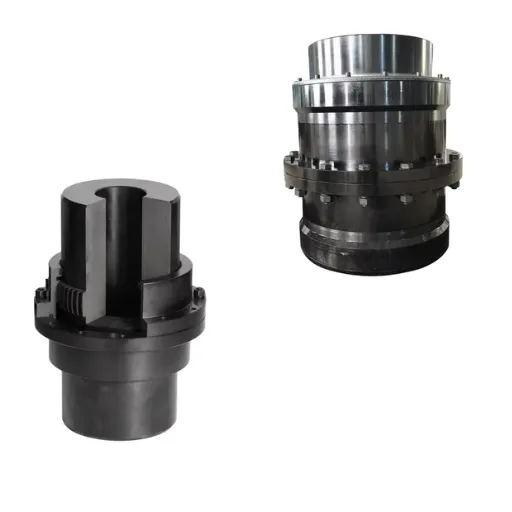
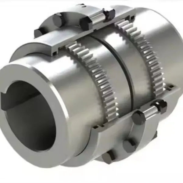
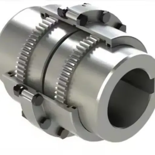
A GIICL drum gear coupling is a flexible shaft connector that transmits torque through crowned external gear teeth on two hubs meshing with internal teeth in a connecting sleeve. The drum-shaped (crowned) tooth profile allows the coupling to compensate for angular, radial, and axial misalignment while carrying high torque in a compact envelope.
The GIICL series follows the Chinese mechanical industry standard JB/T 8854.2 and improves on the earlier GICL design with better sealing and lubricant retention. GIICL couplings are widely used in rolling mills, crushers, kilns, cranes, pumps, and compressors where high torque and shock loads are routine.
Hebei Suju manufactures the GIICL drum gear coupling series from forged alloy steel, with induction-hardened teeth and full dimensional inspection before shipment.
GIICL vs GICL: What the Improved Design Changed
Buyers comparing catalogs often see both GICL and GIICL designations. The two share the same basic drum gear tooth concept, but the GIICL series was developed to address weaknesses in the older GICL design.
The main improvements are:
Better sealing: GIICL couplings use improved end cover seals that retain grease longer and keep dust and moisture out of the tooth mesh.
Longer lubrication intervals: Better lubricant retention means less frequent regreasing in dusty environments such as cement and mining plants.
Higher reliability under misalignment: Refined tooth geometry distributes contact stress more evenly across the crowned tooth face.
For a new installation, GIICL is usually the better default choice. For replacements, note that GIICL and GICL sizes with the same nominal rating are not always dimensionally interchangeable. Check the outer diameter, length, and bolt circle before assuming a direct swap.
GIICL Drum Gear Coupling Specifications Explained
Every GIICL catalog table contains five core specifications. Understanding what each one actually limits is the difference between a coupling that lasts ten years and one that fails in ten weeks.
1. Rated Torque (Nominal Torque)
Rated torque is the maximum continuous torque the coupling can transmit under normal operating conditions, expressed in Newton-meters (N·m). Across the GIICL series, rated torque ranges from a few hundred N·m on the smallest sizes to several hundred thousand N·m on the largest.
Two rules apply when using this number. First, always size the coupling to the adjusted torque: the nominal drive torque multiplied by the application service factor (typically 1.5 to 3.0 for heavy machinery, with guidance available from AGMA publications). Second, never use rated torque as a fatigue limit. A coupling running continuously at 95% of its rated torque will wear far faster than one running at 60%.
2. Bore Diameter Range
Each GIICL size accepts a range of shaft diameters, from a minimum bore to a maximum bore. The maximum bore is limited by the hub wall thickness: boring beyond the published maximum weakens the hub and can cause cracking under load.
When specifying, provide the exact shaft diameters with tolerances and the keyway dimensions. If your shaft exceeds the maximum bore of the size that meets your torque requirement, move up one size rather than asking for an over-limit bore. For genuinely oversized shafts, a drawing-based customization can adapt the hub design safely.
3. Maximum Allowable Speed
Maximum speed, given in RPM, is the highest rotational speed at which the coupling can operate safely in standard, unbalanced condition. Smaller GIICL sizes tolerate several thousand RPM; the largest sizes are limited to a few hundred RPM because of their mass and diameter.
If your application runs above the published standard speed, the coupling needs dynamic balancing to the appropriate ISO grade. High-speed pump drives, test stands, and turbo machinery are the usual cases. Specify the actual operating speed, not the motor nameplate speed, when requesting a quote.
4. Misalignment Allowances
GIICL drum gear couplings compensate for three types of misalignment:
Angular misalignment: typically up to 1.5 degrees for standard designs.
Radial misalignment: a few millimeters, increasing with coupling size.
Axial movement: accommodates thermal expansion and shaft end float.
These allowances are not targets. Operating continuously near the maximum misalignment accelerates tooth wear and shortens lubricant life. Measure the actual shaft misalignment during installation and correct it to well within the coupling's limits. Our guide on measuring shaft misalignment explains the procedure.
5. Materials, Hardness, and Weight
Catalog tables also list the coupling's outer diameter, overall length, and weight. What they often do not list is the material and heat treatment, which determine whether the published torque rating is actually achievable in service.
Hebei Suju machines GIICL hubs and sleeves from forged alloy steel such as 42CrMo or equivalent, with teeth induction hardened or carburized to the specified surface hardness. Weight matters too: a heavier coupling adds rotating mass, which affects startup loads and bearing forces on long overhung shafts.
The specification behind the specification is the manufacturing process that achieves it:
Forging or bar-stock preparation establishes sound grain structure in the hubs and sleeves.
Rough machining brings each part close to final dimensions before heat treatment.
Heat treatment hardens the tooth surface while keeping the core tough enough to absorb shock.
Finish machining cuts the final tooth profile, bores, and keyways to tolerance.
Inspection verifies dimensions, hardness, and surface finish before assembly and packing.
When two suppliers quote the same GIICL size at very different prices, the difference usually hides in these five steps, not in the catalog table.
Representative GIICL Drum Gear Coupling Specifications Table
The table below shows representative values for common GIICL sizes to illustrate how the specifications scale. Exact figures vary by manufacturer and standard revision, so always confirm final values against the manufacturer's current catalog before ordering.
| Size | Rated Torque (N·m) | Max Bore (mm) | Max Speed (RPM) | Typical Application |
|---|---|---|---|---|
| GIICL1 | 400 | 50 | 4,000 | Small pumps, fans |
| GIICL3 | 1,120 | 70 | 4,000 | Compressors, conveyors |
| GIICL5 | 5,000 | 100 | 3,300 | Mixers, medium crushers |
| GIICL8 | 14,000 | 130 | 2,300 | Rolling mill auxiliaries |
| GIICL10 | 22,400 | 150 | 2,000 | Ball mills, hoists |
| GIICL15 | 80,000 | 200 | 1,400 | Main rolling mill drives |
| GIICL20 | 224,000 | 250 | 950 | Heavy crushers, kilns |
Selecting a size for a live project? Send your torque, speed, and shaft data with a quotation request, and our engineers will confirm the correct GIICL size within 24 hours.
How to Use the Specifications to Select a Size
Selection is a sequence, not a guess. Each step eliminates one failure mode, and skipping a step simply moves the failure to a different part of the drive line. Follow these steps with the catalog table in hand:
Calculate nominal torque from motor power and operating speed. For example, a 500 kW motor at 500 RPM produces approximately 9,550 N·m.
Apply the service factor for your application. A ball mill with frequent shock loading might use 2.0, giving a required rating of 19,100 N·m.
Find the smallest size whose rated torque meets or exceeds the adjusted value. In this example, GIICL10 at 22,400 N·m qualifies; GIICL8 at 14,000 N·m does not.
Check the bore against your shaft diameters. If the shaft exceeds the maximum bore, move up a size.
Verify speed and misalignment against the published limits, including any balancing requirements.
This process is the same one our engineering team runs when reviewing customer inquiries. For a deeper treatment of service factors and environment, see our guide on how to select a gear coupling for heavy machinery.
A procurement manager at a Vietnamese steel plant, Linh, used exactly this method in early 2026 for a rolling mill drive replacement. Her calculated requirement was 17,800 N·m after applying the service factor. The failed coupling on the mill was equivalent to GIICL8, rated at 14,000 N·m, which explained its repeated tooth wear. She specified GIICL10, and the drive has run without a single unplanned stop since.
When Standard Specifications Are Not Enough
Standard GIICL sizes cover most heavy-industry applications, but four situations call for modified specifications:
Non-standard shaft sizes beyond the maximum published bore.
Special spacer lengths to bridge an unusual distance between shaft ends.
Higher speed operation requiring dynamic balancing and tighter runout tolerances.
Harsh environments that demand special seals, coatings, or materials.
In these cases, the catalog table is a starting point, not the final answer. Hebei Suju produces custom GIICL variants from customer drawings or worn samples, adjusting bore, length, material, and balancing to the application. Each custom coupling follows the same documented process as our standard series, verified through full-process quality control with dimensional and hardness inspection reports available on request.
Common Mistakes When Reading GIICL Specifications
The failure modes behind most early coupling failures trace back to a handful of specification errors:
Sizing by bore diameter alone. A bore that fits says nothing about torque capacity, as Ravi's ball mill case shows.
Skipping the service factor. Nominal motor torque understates real loading in shock applications. The adjustment is not optional.
Treating misalignment limits as operating targets. The published limits are maximums for occasional excursions, not continuous working points.
Ignoring the speed rating on retrofits. A replacement coupling on a drive that was later uprated to higher RPM may exceed the original size's speed limit.
Assuming GICL and GIICL swap directly. Similar ratings do not guarantee identical dimensions or bolt patterns.
Avoiding these mistakes costs nothing beyond a careful read of the catalog table and a few questions to the manufacturer.
Conclusion
GIICL drum gear coupling specifications only protect your equipment when you read them together. Keep these takeaways in mind:
Size by adjusted torque (nominal torque times service factor), never by bore alone.
Respect the maximum bore; move up a size instead of over-boring the hub.
Check speed and misalignment limits against actual operating conditions.
Confirm material grade and tooth hardness, not just the catalog rating.
Use custom specifications when standard sizes cannot match the application.
Ravi's ball mill failure cost six weeks of production because one number in a catalog table was read in isolation. Fifteen minutes of specification review would have prevented it.
If you have a drive to specify, send us the torque, speed, bore, and application details for a free engineering review. Request a quotation for standard GIICL sizes, or send us your drawing for custom specifications. Our team responds to standard inquiries within 24 hours.
Recently Posted
-
Jaw Coupling Spider Replacement: A Step-by-Step Maintenance Guide
July 28, 2026A maintenance technician at a packaging plant in Brazil noticed vibration on a motor-pump set during his morning rounds. The motor Read More
 -
Flexible Coupling for Motor Pump Sets: A Selection Guide
July 28, 2026A maintenance manager at a water treatment plant in Southeast Asia called us after replacing motor pump couplings three times in 1 Read More
 -
Flexible Shaft Coupling: Selection Guide for Industrial Drives
July 28, 2026When two rotating shafts are connected directly, even a small amount of misalignment can generate vibration, bearing load, and pre Read More
 -
Elastic Coupling: Vibration Control for Industrial Drives
July 28, 2026When a motor-pump set starts vibrating above acceptable limits, the first checks usually fall on bearing wear, impeller balance, o Read More

Contact Us
Recommended Products
-
 OEM Customizable Cardan Shaft Coupling Flexible Rigid Steel for Air Compressor Propeller Universal Construction Printing ShopsNegotiableMOQ: 2 Pieces
 -
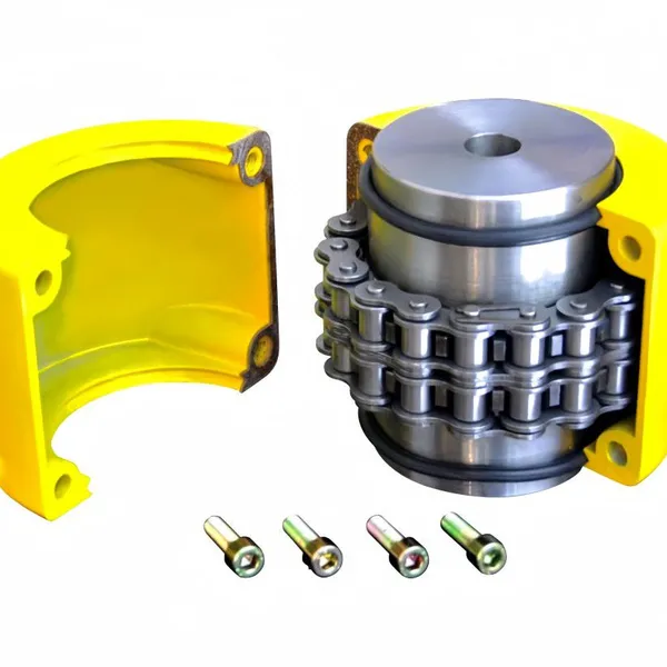
Kc Coulpling Roller Chain Coupling Set With Chain and Sprocket for General MachineryNegotiableMOQ: 1 Piece
-
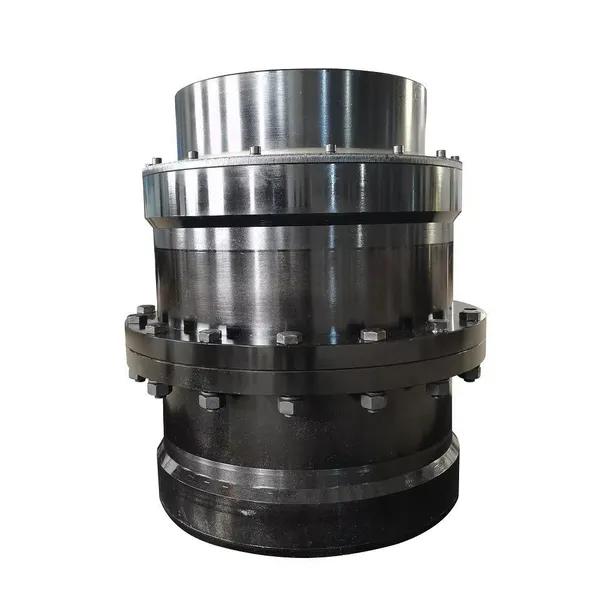
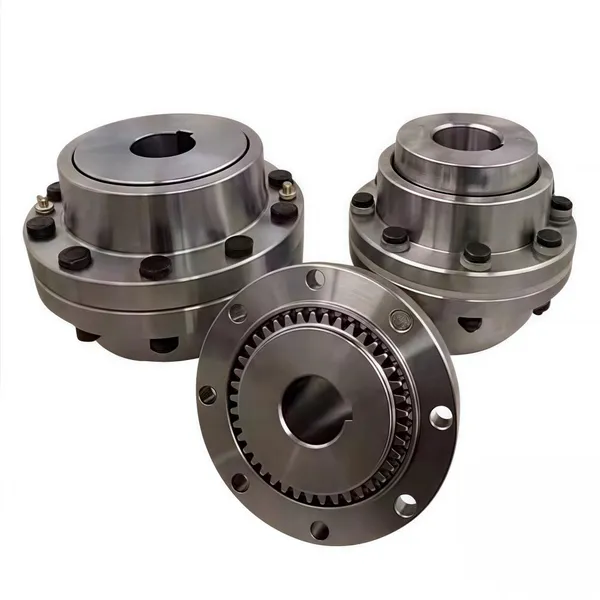
High Transmission Efficiency Drum Gear Coupling Easy Installation Gear Coupler For Heavy MachineryNegotiableMOQ: 10 Pieces
-
High-Torque Roller Chain Coupling Durable Steel Aluminium Construction Customizable Precision Engineering OEM Shaft CouplingsNegotiableMOQ: 2 Pieces
-
Customizable Rigid Iron Steel Aluminium Rubber Tyre Coupling OEM Support for Pumps Industrial Equipment Construction IndustriesNegotiableMOQ: 10 Pieces
-
Jsb Flexible Grid Coupling With Metallic Elastic Element Factory Direct Spider Snake Spring CouplingNegotiableMOQ: 10 Pieces
-
High Torque JQ/JQW Type Clamp Coupling for Motor & Gearbox 45 Steel Jacketed Iron Disc Structure Flexible Rigid OEM SupportedNegotiableMOQ: 2 Pieces
-
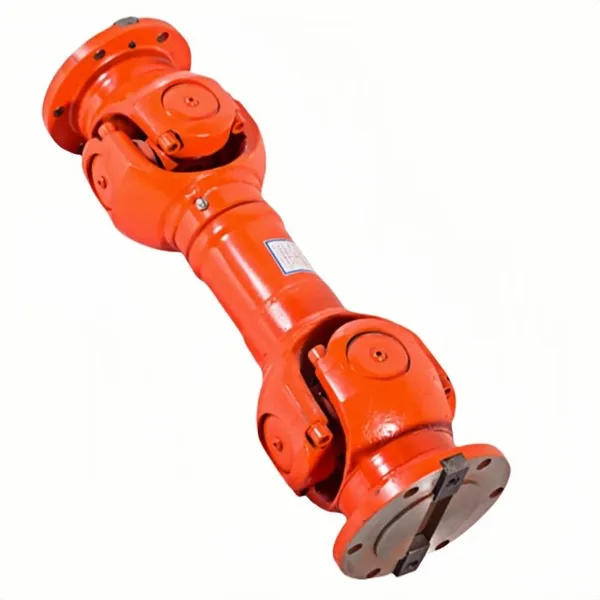
SWC Series Flange Universal Joint Coupling Hardened Cross Shaft Heavy Duty TransmissionNegotiableMOQ: 1 Piece
-
Heavy Duty Universal Coupling High Quality Universal Shaft for Machinery and EquipmentNegotiableMOQ: 1 Piece
-
OEM Customized Precision Cast Iron Zinc Aluminum Die Castings New Hydraulic Parts Fittings 1 Year WarrantyNegotiableMOQ: 100 Pieces
-
Yl Series Rigid Flange Coupling Power Transmission PartsNegotiableMOQ: 2 Pieces
-
Flange Coupling for Water Pump and Compressor Applications With Rubber Gasket SealNegotiableMOQ: 2 Pieces
-
Heavy-Duty Telescopic Welding Cardan Shaft for Universal UseNegotiableMOQ: 1 Piece
-
Flexible Universal Shaft Flange Coupling for Marine and Industrial Drive SystemsNegotiableMOQ: 10 Pieces
-
Durable Expansion Sleeve, Locking Assembly & Taper Lock Bushing for Robotic Arm JointsNegotiableMOQ: 1 Piece
-
High Quality Yl Type Rigid Flange Coupling Mechanical Transmission CouplingNegotiableMOQ: 2 Pieces
-
Stainless Steel Flexible Universal Joint Coupling for Motor Flange Gear Pump and Spline ShaftNegotiableMOQ: 1 Piece
-
Compact Drum Gear Coupling for Heavy Industrial Transmission High Torque CapacityNegotiableMOQ: 10 Pieces
-
Standard or Customized Jaw Beam (Helical) Flexible Coupling for General MachineryNegotiableMOQ: 10 Pieces
-
TL Series Elastic Pin Coupling Easy Replace Rubber Bush Coupling With Shaft Misalignment CompensationNegotiableMOQ: 10 Pieces