
 Business License
Coupling Replacement Guide: Diagnose, Remove, and Install Correctly
The motor was running, but the pump was not. Maintenance supervisor David Chen traced the problem to a vibrating gear coupling between the motor and gearbox. The teeth were chipped, the grease was contaminated with metal particles, and the line was down. His team had 12 hours before the next production shift started.
A coupling replacement isn't just about swapping one part for another. The wrong replacement, poor alignment, or a missed root cause will send the maintenance team back within weeks. This coupling replacement guide walks you through how to diagnose failure, remove the old coupling safely, select the right replacement, and install it so the drive runs reliably.
In this article, you'll learn the warning signs that a coupling needs replacement. You'll also learn how to inspect and diagnose common failure modes, follow the correct removal and installation procedure, and decide when a custom replacement is the better option.
Whether you're maintaining pumps, compressors, conveyors, or heavy rolling mill drives, these steps will help you complete the repair correctly the first time.
When Does a Coupling Need Replacement?
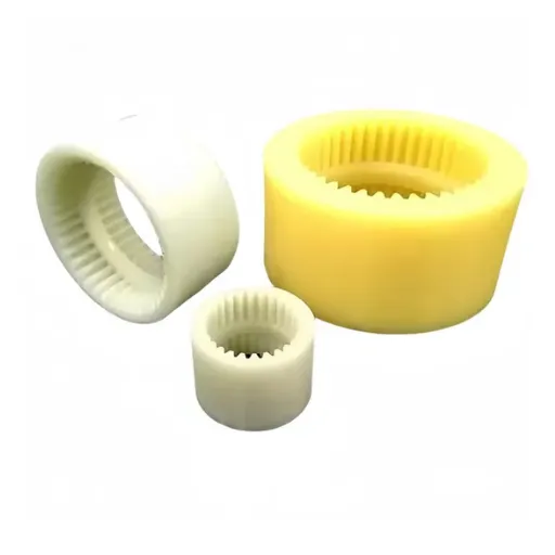
Couplings are designed to absorb misalignment, dampen vibration, and protect connected equipment. Over time, wear, fatigue, and environmental damage reduce their effectiveness. Knowing when to replace a coupling before it fails completely prevents unplanned downtime and secondary damage to motors, gearboxes, and bearings.
Common Coupling Failure Signs
Watch for these coupling failure signs during routine inspections and operation:
Excessive vibration: Unusual vibration in the drive train often means the coupling is worn, misaligned, or unbalanced.
Unusual noise: Grinding, clicking, or squealing sounds can indicate metal-to-metal contact, worn elastomer elements, or loose fasteners.
Visible wear or damage: Cracked elastomer spiders, chipped gear teeth, worn hubs, or corroded surfaces are clear signs.
Overheating: A hot coupling may signal insufficient lubrication, excessive misalignment, or overload.
Grease contamination: Metal particles, water, or dust in the lubricant indicate internal wear or seal failure.
Shaft movement: Excessive axial or radial play at the coupling suggests worn bearings or a failed flexible element.
At Hebei Suju, we often receive samples from maintenance teams who waited too long. A worn drum gear coupling from a steel mill may look intact from the outside while the teeth are severely worn inside. Regular inspection catches this before catastrophic failure.
Inspection Frequency
The right inspection interval depends on application severity. As a general rule:
Light-duty pump and fan drives: Quarterly visual inspection.
General industrial machinery: Monthly visual check and annual vibration measurement.
Heavy-duty crushers, rolling mills, and kilns: Monthly inspection and quarterly vibration analysis.
Critical continuous-process drives: Continuous vibration and temperature monitoring.
For example, a water treatment plant running three centrifugal pumps might inspect flexible couplings every three months. A steel rolling mill running 24 hours per day might inspect gear couplings weekly and measure vibration monthly. Match the inspection frequency to the cost of failure, not just the calendar.
Pro Tip: Always inspect both the coupling and the connected equipment. A coupling failure is often a symptom of misalignment, bearing wear, or overload, not just a worn part.
Diagnosing Coupling Failure Modes
Before ordering a replacement, identify why the original coupling failed. Replacing a coupling without fixing the root cause leads to repeat failures. The failure pattern tells you what went wrong.
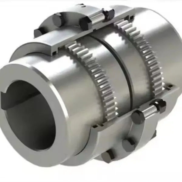
Tooth Wear and Fatigue in Gear Couplings
Gear couplings fail when teeth wear, pit, or chip. Common causes include:
Inadequate lubrication: Dry or contaminated grease accelerates tooth wear.
Excessive misalignment: Operating beyond the coupling's rated angular or radial capacity causes edge loading.
Overload: Peak torque above the rated value leads to tooth deformation or fracture.
High cycle fatigue: Millions of load cycles eventually cause surface pitting or cracking.
A gear coupling with polished tooth flanks may indicate normal wear. Sharp edges, pitting, or chipped teeth point to overload or misalignment. For GIICL drum gear couplings, inspect the crown profile. Loss of crown shape reduces misalignment capacity and increases contact stress. Gear coupling ratings and inspection practices from AGMA provide a useful reference for evaluating tooth condition and load capacity.
Elastomer Degradation in Flexible Couplings
Flexible couplings use rubber or polyurethane elements that degrade over time. Look for:
Cracking or hardening: Heat, ozone, and age cause elastomer spiders to crack.
Compression set: Permanent deformation reduces damping and misalignment capacity.
Chemical attack: Oils, solvents, or process fluids can swell or dissolve the elastomer.
At Hebei Suju, we supply flexible couplings with different spider materials. Replacing a standard spider with one suited to the environment can extend service life significantly.
Bolt Loosening and Hub Damage
In all coupling types, bolt loosening causes vibration, hub movement, and eventual damage. Causes include:
Insufficient bolt torque during installation
Thermal cycling loosening fasteners
Wrong bolt grade or threadLocker not applied
Hub bore damage from improper fit or removal
Check the hub bore for scoring, galling, or out-of-roundness. A damaged hub must be replaced or repaired. Do not install a new coupling on a damaged shaft.
Environmental and Application Factors
Sometimes the coupling did nothing wrong. The application changed. For example:
Production rate increases raised torque demand.
Equipment relocation changed shaft alignment.
Process changes introduced chemicals or temperature extremes.
A motor upgrade increased starting torque.
When the application changes, the original coupling may no longer be suitable. In that case, request a quotation with full application details so the replacement can be re-specified.
Removing the Old Coupling Safely
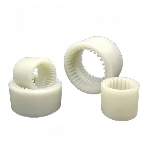
Safe removal protects personnel, shafts, bearings, and surrounding equipment. Rushing this step is a common cause of secondary damage. Following this part of the coupling replacement guide will help you avoid scraped bores, bent shafts, and damaged bearings. Those problems often turn a simple repair into a major rebuild.
Step 1: Lock Out and Tag Out
Before touching the coupling:
Shut down the drive and isolate power.
Apply lockout/tagout procedures to motors and controls.
Verify zero mechanical energy. Ensure shafts can't rotate.
Allow the machine to cool if it was running.
Step 2: Inspect the Installed Assembly
Photograph the coupling from multiple angles before disassembly. Note the position of hubs, spacers, bolts, keys, and seals. Measure shaft gaps and axial positions. This documentation simplifies installation of the new coupling.
Step 3: Remove Fasteners and Accessories
Remove guards, covers, lubrication fittings, and seals first. Then remove coupling bolts in a star pattern to avoid distorting the hub. For tapered or interference-fit hubs, use a puller. Never strike the coupling directly with a hammer. If heat is needed to release a tight fit, apply controlled heat to the hub, not the shaft. If you need to replace gear coupling sleeves or hubs, support them before disconnecting. This prevents them from hanging on the shaft and galling the bore.
Step 4: Inspect the Shafts and Bearings
With the coupling removed, inspect the shaft ends for:
Wear, scoring, or corrosion under the hubs
Correct diameter and tolerance
Keyway condition
End float and radial runout
Measure shaft runout with a dial indicator. Excessive runout indicates bearing wear or bent shafts that must be corrected before installing the new coupling.
Safety Note: Some couplings are heavy. Use appropriate lifting equipment for large gear couplings and cardan shafts. Dropping a coupling can damage the shaft, the coupling, or nearby personnel.
Tools and Documentation to Prepare Before Replacement
A smooth coupling replacement depends on preparation. Before you start, gather the right tools and documentation. Missing a puller, torque wrench, or correct bolt grade mid-job turns a two-hour repair into a day-long delay.
Essential Tools
Dial indicator or laser alignment kit: For verifying shaft alignment after installation.
Torque wrench: Calibrated and sized for the coupling bolts.
Hub puller or hydraulic puller: For removing interference-fit hubs without damage.
Cleaning supplies: Solvent, rags, scrapers, and fine abrasive paper for shaft preparation.
Measuring tools: Calipers, micrometers, and feeler gauges for checking bores and gaps.
Lifting equipment: Slings, chains, or a small hoist for heavy couplings.
Thread-locking compound and anti-seize: For fasteners and hub bores as specified.
Documentation to Collect
Original coupling drawing or catalog page
Equipment manual with torque specifications
Previous maintenance records and failure history
Motor nameplate data (power, speed, and service factor)
Alignment records from the last installation
Having this information on hand helps you avoid mistakes and speeds up communication with the manufacturer if you need a custom replacement coupling.
Selecting the Right Replacement Coupling
Selecting a replacement coupling is more than matching the part number. The replacement must fit the shafts, handle the load, tolerate the misalignment, and survive the environment.
Option 1: Direct Catalog Replacement
If the original coupling was correctly specified and the application hasn't changed, a direct catalog replacement is usually the fastest solution. Confirm:
Coupling type and size
Bore diameter and keyway dimensions
Overall length and spacer requirements
Rated torque and maximum speed
Material and heat treatment requirements
For common industrial drives, Hebei Suju supplies standard flexible couplings and drum gear couplings in standard bore and torque ranges.
Option 2: Re-specify for Changed Conditions
If operating conditions have changed, the original size may be undersized. Re-specify when:
Motor power or speed has increased
Duty cycle is more severe
Misalignment is greater than originally assumed
Ambient temperature or contamination has increased
The coupling failed repeatedly despite correct installation
In these cases, consult the manufacturer's technical team. Upgrading to a larger size, different coupling type, or enhanced materials may be necessary.
Option 3: Custom Replacement Coupling
Some replacement scenarios don't fit any catalog. The original manufacturer may have discontinued the part, or the shaft dimensions may be non-standard. A custom replacement coupling manufactured from a drawing or worn sample solves this problem.
At a mining operation in South America, the maintenance team couldn't find a replacement for an obsolete crusher coupling. The bore was imperial, the spacer length was unusual, and no standard catalog matched. They shipped the worn coupling to Hebei Suju, where engineers reverse-engineered the dimensions and produced a 42CrMo alloy steel replacement.
The fit was verified on site, and the crusher restarted within the planned shutdown window. This worn coupling replacement was produced from the original sample, so the bore, keyway, and spacer length matched the crusher exactly.
Selection Checklist
Use this checklist when ordering a replacement coupling:
Shaft diameters and keyway sizes confirmed
Torque, speed, and service factor calculated
Expected angular, radial, and axial misalignment documented
Operating environment described (temperature, dust, moisture, chemicals)
Space constraints including spacer length checked
Material and heat treatment requirements specified
Quantity and delivery schedule communicated
Coupling Installation and Shaft Alignment
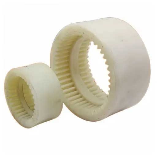
Proper installation determines how long the replacement coupling will last. Even a high-quality coupling will fail early if it's misaligned, poorly lubricated, or improperly bolted. A methodical coupling installation procedure prevents the misalignment, uneven bolt torque, and lubrication errors that cause early failures.
Step 1: Prepare the Shafts
Clean the shaft ends, hubs, and keyways. Remove burrs, corrosion, and old lubricant. Inspect keys for proper fit. Apply a thin film of anti-seize compound to the shaft bore interface for future removal, unless the manufacturer specifies otherwise.
Step 2: Mount the Hubs
Install the hubs on their respective shafts. For interference fits, heat the hub uniformly or use a press. Don't hammer the hub into place. Ensure the hub sits at the correct axial position. Verify that the key is fully seated and that the hub doesn't bind.
Step 3: Align the Shafts
Shaft alignment is one of the most important steps in a coupling replacement. Misalignment causes vibration, heat, and premature wear. Even a coupling rated for misalignment will last longer when it's operating near the aligned position. Choosing the right shaft alignment coupling method (laser, dial indicator, or straightedge) depends on the speed, power, and precision requirements of the drive.
Use one of these methods based on application criticality:
Straightedge and feeler gauge: Acceptable for low-speed, low-tolerance drives where exact precision isn't required.
Dial indicators: More accurate for general industrial equipment. Use the rim-and-face or reverse-dial method depending on coupling geometry.
Laser alignment tools: Recommended for high-speed, high-power, or precision drives. They provide immediate feedback and reduce human error.
Check alignment in both the horizontal and vertical planes. Correct angular misalignment first, then radial offset. Recheck after tightening hold-down bolts, as soft foot can shift the machine. ISO alignment standards define tolerance classes for different machine speeds and can help you set acceptable targets for your application.
Soft foot occurs when one foot of the motor or driven machine doesn't sit flat on the base. It can distort the frame and create misalignment even when the coupling appears aligned. Shim the feet until all four sit evenly before final alignment.
For thermal growth, consider the operating temperature of the equipment. A motor shaft may rise slightly as it heats up. Some laser alignment systems can compensate for expected thermal movement.
Step 4: Install the Flexible Element or Spacer
For flexible couplings, install the spider, tire, diaphragm, or bushing element according to the manufacturer's instructions. For gear couplings, apply the correct lubricant before assembling the sleeve and seals. For spacer couplings, verify the spacer length matches the shaft gap.
Step 5: Torque Bolts to Specification
Use a calibrated torque wrench and tighten coupling bolts in a star pattern. Uneven torque causes hub runout and vibration. Apply thread-locking compound if specified. Re-torque after the first few hours of operation, especially on new installations.
Step 6: Verify Installation
Rotate the shafts by hand to confirm smooth movement. Check for interference between the coupling and guards or nearby components. Start the drive at low speed and monitor vibration, temperature, and noise. Schedule a follow-up inspection after the first 50 operating hours.
Coupling Maintenance and Failure Prevention
The best coupling replacement is the one you don't have to repeat. Preventive maintenance and correct specification extend coupling life and reduce downtime. Good coupling maintenance is the most cost-effective way to extend service life, because it catches misalignment, contamination, and overload before they destroy the drive.
Lubrication Management
Gear couplings depend on proper lubrication. Follow the manufacturer's recommendation for grease or oil type, quantity, and change interval. Inspect seals regularly and replace them before contamination enters the coupling. For severe environments, consider sealed or enhanced lubrication systems.
When regreasing, don't overfill. Excess grease creates internal pressure that can blow out seals. Use the recommended grease grade for the operating temperature. In hot applications, high-temperature grease prevents breakdown. In cold climates, low-temperature grease maintains flow.
Alignment Monitoring
Shaft alignment changes over time due to foundation settling, thermal expansion, and bearing wear. Re-check alignment during scheduled shutdowns. For critical drives, continuous vibration monitoring catches misalignment early.
Trend vibration data over time. A gradual increase in vibration often indicates progressive misalignment, bearing wear, or coupling degradation. Catching the trend early lets you schedule maintenance before failure.
Load and Duty Review
If the drive has been uprated or the process has changed, review the coupling specification. A coupling that was adequate at original design may be undersized after years of production increases. Document torque peaks, starts per hour, and reversing cycles. Share this data with the manufacturer when ordering replacements.
For example, a conveyor that originally ran eight hours per day may now run continuously. The increased duty cycle shortens coupling life even if the torque appears unchanged. A higher service factor or larger coupling size may be warranted.
Use Quality Replacement Parts
Not all replacement couplings are equal. Bargain parts may use inferior materials, skip heat treatment, or lack dimensional accuracy. At Hebei Suju, our full-process quality control covers material inspection, machining, heat treatment, dimensional checks, and final testing. We provide material certificates and inspection reports on request, so you know the replacement meets specification.
Keep Critical Spares in Stock
For essential drives, keep one spare coupling or key wear elements on site. Waiting for a replacement part during a breakdown adds days to downtime. If your coupling is custom or obsolete, consider ordering a spare when you place the replacement order.
A spare coupling stored in the warehouse costs far less than lost production. Store it in a clean, dry location away from direct sunlight and chemicals. Elastomer elements should be replaced according to shelf-life recommendations even if they haven't been installed.
When to Call the Manufacturer
Some coupling replacements are straightforward. Others need expert input. Contact the manufacturer when:
The original coupling is obsolete or unidentifiable.
Shaft dimensions are non-standard.
The application conditions have changed significantly.
You need help interpreting failure mode evidence.
You want to upgrade materials or design for longer life.
The coupling has failed repeatedly and you're not sure why.
At Hebei Suju, our engineering team reviews customer drawings and samples to recommend the right replacement. If you have a worn coupling or drawing, send it to us for a technical review and quotation. We'll check manufacturability, suggest materials, and provide a clear lead time.
Frequently Asked Questions
How do I know when a coupling needs replacement?
Look for common coupling failure signs: excessive vibration, unusual noise, visible wear or cracks, overheating, contaminated grease, and excessive shaft movement. Regular inspection catches these before catastrophic failure.
What is the most common cause of gear coupling failure?
Inadequate lubrication and excessive misalignment are the most common causes. Dry or contaminated grease accelerates tooth wear, while misalignment beyond the coupling's rated capacity causes edge loading and fatigue.
How often should couplings be inspected?
Light-duty drives need quarterly visual checks. General industrial machinery benefits from monthly inspections plus annual vibration measurement. Heavy-duty crushers, rolling mills, and kilns should be inspected monthly and analyzed quarterly.
Can a worn coupling be repaired instead of replaced?
Some flexible elements, seals, and bolts can be replaced. However, worn gear teeth, damaged hubs, or distorted bores usually require a full replacement. Repairing a worn coupling without addressing misalignment or overload simply delays the next failure.
Conclusion
A successful coupling replacement starts with diagnosis, not disassembly. Inspect the failed coupling to understand why it wore out. Check the shafts, bearings, and alignment before installing the new unit. Select a replacement that matches the current application, not just the original catalog number.
This coupling replacement guide covered the warning signs of failure, common failure modes, safe removal procedures, selection criteria, installation and alignment steps, and preventive measures. Follow this process to reduce repeat failures and keep your drives running reliably.
At Hebei Suju, we support maintenance teams and OEM engineers with standard and custom couplings for industrial machinery. From catalog replacements to reverse-engineered custom parts, we manufacture couplings that match your equipment and your schedule.
Recently Posted
-
Jaw Coupling Spider Replacement: A Step-by-Step Maintenance Guide
July 28, 2026A maintenance technician at a packaging plant in Brazil noticed vibration on a motor-pump set during his morning rounds. The motor Read More
 -
Flexible Coupling for Motor Pump Sets: A Selection Guide
July 28, 2026A maintenance manager at a water treatment plant in Southeast Asia called us after replacing motor pump couplings three times in 1 Read More
 -
Flexible Shaft Coupling: Selection Guide for Industrial Drives
July 28, 2026When two rotating shafts are connected directly, even a small amount of misalignment can generate vibration, bearing load, and pre Read More
 -
Elastic Coupling: Vibration Control for Industrial Drives
July 28, 2026When a motor-pump set starts vibrating above acceptable limits, the first checks usually fall on bearing wear, impeller balance, o Read More

Contact Us

Recommended Products
-
 OEM Customizable Cardan Shaft Coupling Flexible Rigid Steel for Air Compressor Propeller Universal Construction Printing ShopsNegotiableMOQ: 2 Pieces
 -
Kc Coulpling Roller Chain Coupling Set With Chain and Sprocket for General MachineryNegotiableMOQ: 1 Piece
-
High Transmission Efficiency Drum Gear Coupling Easy Installation Gear Coupler For Heavy MachineryNegotiableMOQ: 10 Pieces
-
High-Torque Roller Chain Coupling Durable Steel Aluminium Construction Customizable Precision Engineering OEM Shaft CouplingsNegotiableMOQ: 2 Pieces
-
Customizable Rigid Iron Steel Aluminium Rubber Tyre Coupling OEM Support for Pumps Industrial Equipment Construction IndustriesNegotiableMOQ: 10 Pieces
-
Jsb Flexible Grid Coupling With Metallic Elastic Element Factory Direct Spider Snake Spring CouplingNegotiableMOQ: 10 Pieces
-
High Torque JQ/JQW Type Clamp Coupling for Motor & Gearbox 45 Steel Jacketed Iron Disc Structure Flexible Rigid OEM SupportedNegotiableMOQ: 2 Pieces
-
SWC Series Flange Universal Joint Coupling Hardened Cross Shaft Heavy Duty TransmissionNegotiableMOQ: 1 Piece
-
Heavy Duty Universal Coupling High Quality Universal Shaft for Machinery and EquipmentNegotiableMOQ: 1 Piece
-
OEM Customized Precision Cast Iron Zinc Aluminum Die Castings New Hydraulic Parts Fittings 1 Year WarrantyNegotiableMOQ: 100 Pieces
-
Yl Series Rigid Flange Coupling Power Transmission PartsNegotiableMOQ: 2 Pieces
-
Flange Coupling for Water Pump and Compressor Applications With Rubber Gasket SealNegotiableMOQ: 2 Pieces
-
Heavy-Duty Telescopic Welding Cardan Shaft for Universal UseNegotiableMOQ: 1 Piece
-
Flexible Universal Shaft Flange Coupling for Marine and Industrial Drive SystemsNegotiableMOQ: 10 Pieces
-
Durable Expansion Sleeve, Locking Assembly & Taper Lock Bushing for Robotic Arm JointsNegotiableMOQ: 1 Piece
-
High Quality Yl Type Rigid Flange Coupling Mechanical Transmission CouplingNegotiableMOQ: 2 Pieces
-
Stainless Steel Flexible Universal Joint Coupling for Motor Flange Gear Pump and Spline ShaftNegotiableMOQ: 1 Piece
-
Compact Drum Gear Coupling for Heavy Industrial Transmission High Torque CapacityNegotiableMOQ: 10 Pieces
-
Standard or Customized Jaw Beam (Helical) Flexible Coupling for General MachineryNegotiableMOQ: 10 Pieces
-
TL Series Elastic Pin Coupling Easy Replace Rubber Bush Coupling With Shaft Misalignment CompensationNegotiableMOQ: 10 Pieces