Rigid Coupling: Types, Selection, and Industrial Applications
A pump manufacturer in Germany once shipped a batch of vertical turbine pumps with rigid couplings installed between the motor and pump shafts. The alignment had been checked on the assembly bench, but thermal growth during operation shifted the motor shaft by 0.15 mm.
Within six months, every coupling showed bearing-side wear, and three motors needed rewinding. The rigid coupling wasn't the wrong product. It was the right product in an application that needed a flexible coupling.
That distinction matters in industrial power transmission. A rigid coupling is the simplest, most direct way to connect two shafts, but it only works when the shafts stay aligned. In the right application, it delivers zero backlash, high torque density, and minimal maintenance. In the wrong application, it transfers misalignment into bearings, seals, and housings.
In this guide, you'll learn what a rigid coupling is, how it differs from a flexible coupling, which types are available, and how to select one for your drive system. By the end, you'll know when a rigid coupling is the right choice and when you should specify a flexible coupling instead.
What Is a Rigid Coupling?
A rigid coupling is a shaft connector that joins two rotating shafts into a single unit. Unlike a flexible coupling, it has no flexible element and cannot compensate for angular, radial, or axial misalignment. The two shafts must be aligned within tight tolerances during installation, and they must stay aligned during operation.
This design gives a rigid coupling several advantages. It transmits torque with no backlash. It adds no compliance or wind-up between the driving and driven shafts.
It is compact, simple, and usually less expensive than a flexible coupling of the same torque capacity. For precision positioning, indexing, and well-aligned high-speed drives, a rigid coupling is often the best choice.
Hebei Suju manufactures rigid couplings for pumps, compressors, gearboxes, and precision machinery. Our flanged, sleeved, and clamp-style rigid couplings are machined from forged or bar-stock steel and finished to tight bore and runout tolerances.
How It Works
The working principle is straightforward. The coupling locks the two shaft ends together so they rotate as one. Torque passes directly from the driving shaft through the coupling into the driven shaft. Because there is no flexible element, there is no damping, no misalignment compensation, and no stored spring energy.
The coupling achieves this connection in one of three ways:
Bolting: Flanged hubs are keyed to each shaft and bolted face-to-face.
Compression: A sleeve or clamp is tightened around the two shaft ends.
Interference fit: A tapered sleeve or press-fit hub locks onto the shaft.
The connection is only as good as the alignment. A rigid coupling does not tolerate shaft movement. If thermal expansion, bearing wear, or foundation settling shifts either shaft, the coupling transmits that displacement as force into the bearings and housings.
That force is why rigid couplings demand precision alignment. In most cases, the shafts must be aligned to within a few thousandths of a millimeter. For high-speed drives, the tolerances are even tighter.
Main Rigid Coupling Types
Not all rigid couplings are identical. The hub shape, clamping method, and torque path determine the best application. The most common rigid coupling types used in industry are flanged, sleeve, clamp, and disc rigid couplings.
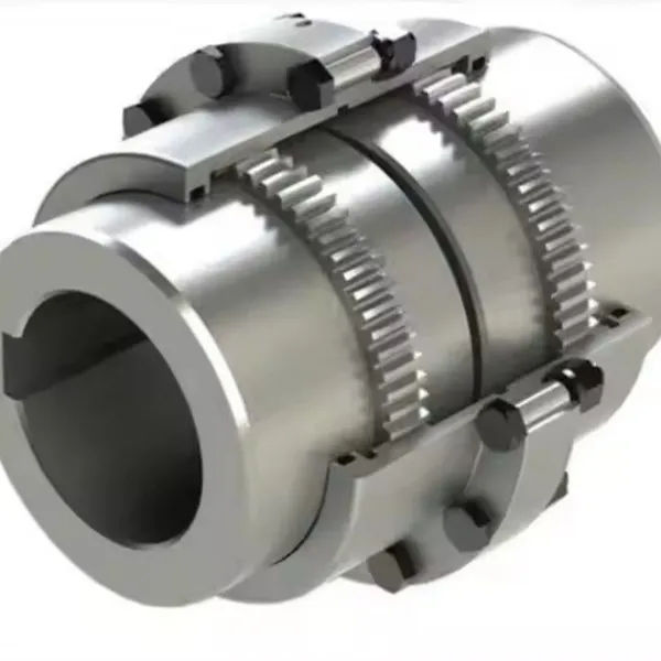
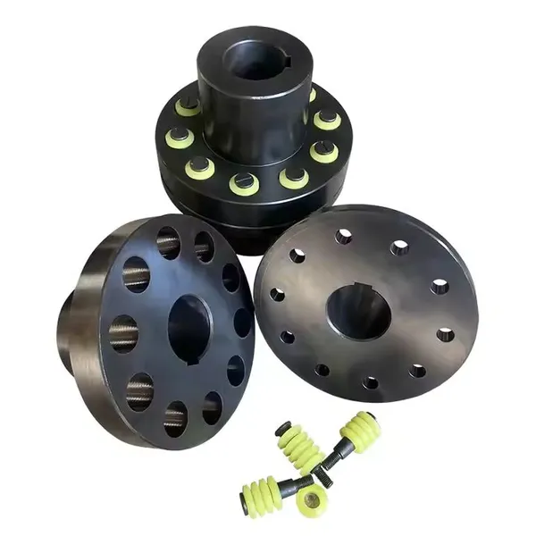
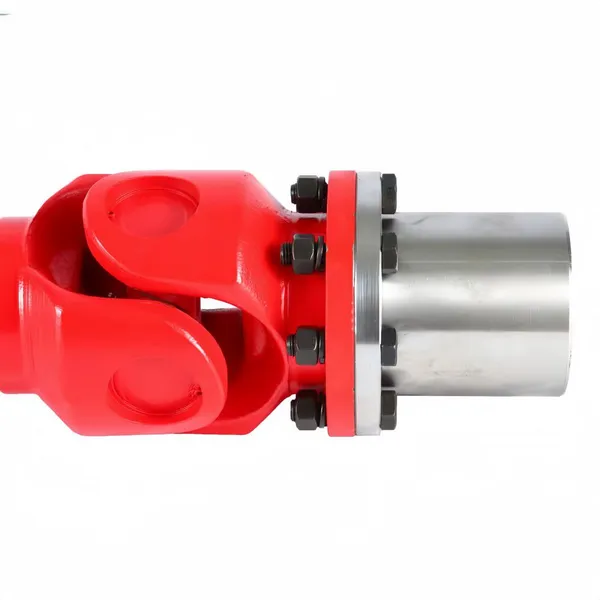
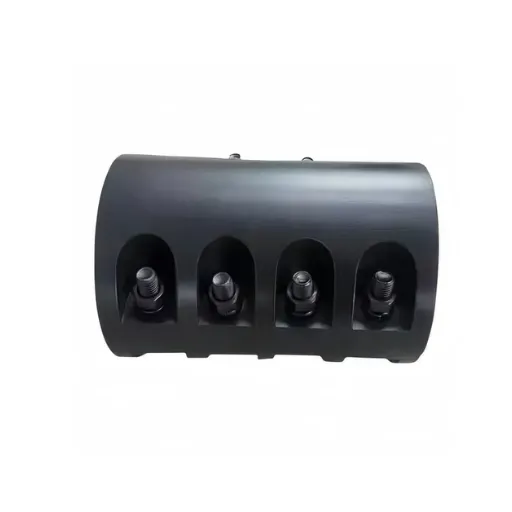
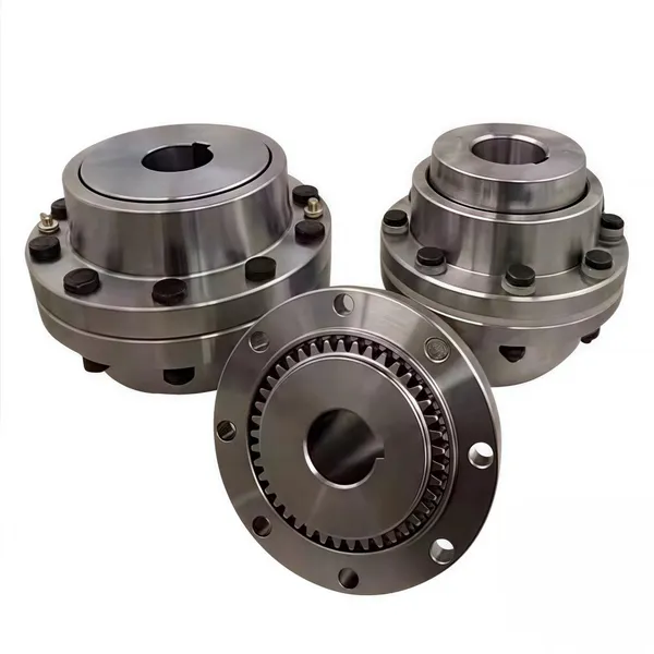
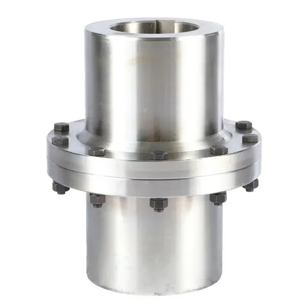
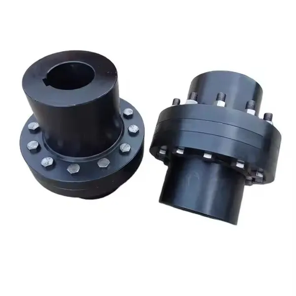
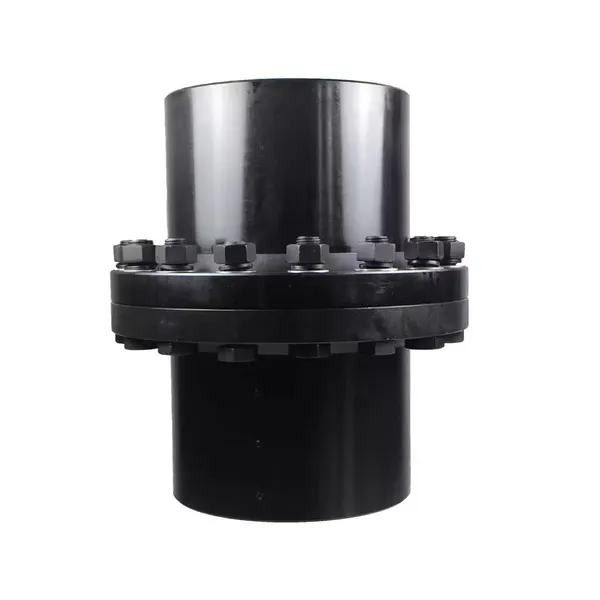
Flange Coupling
A flange rigid coupling uses two flanged hubs keyed to the shaft ends. The hubs are bolted together face-to-face. This is the most common rigid coupling design for medium and large shafts.
Best for: Pumps, compressors, gearboxes, and large motors with good alignment.
Advantages: High torque capacity, simple assembly, easy to disassemble for maintenance.
Limitations: Requires precise alignment, adds axial length, and needs accurate bolt torque.
At Hebei Suju, our flange coupling range covers standard bore sizes and custom bolt-circle patterns for replacement and OEM projects.
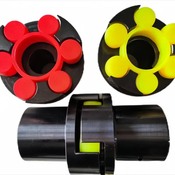
Sleeve Coupling (Muff Coupling)
A sleeve coupling, also called a muff coupling, is a single cylindrical sleeve that fits over the ends of both shafts. It is usually secured with keys and set screws or by an interference fit.
Best for: Light-duty drives, vertical pumps, and small motors.
Advantages: Compact, low cost, no protruding bolts.
Limitations: Lower torque capacity than flanged designs, harder to remove for maintenance.
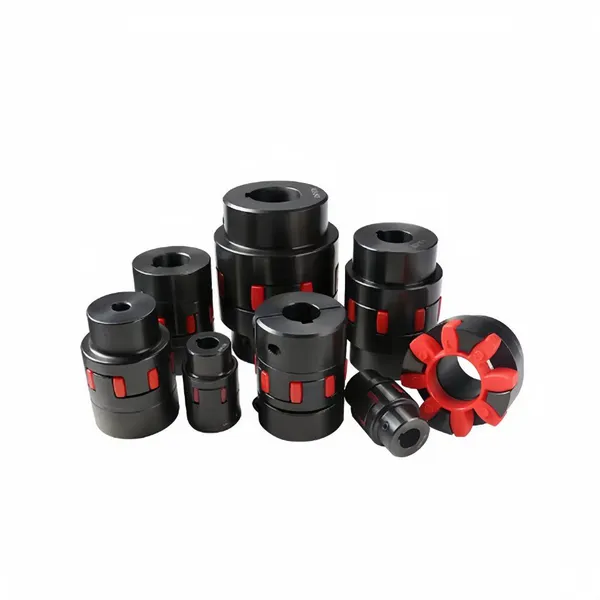
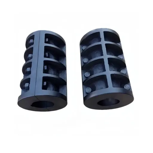
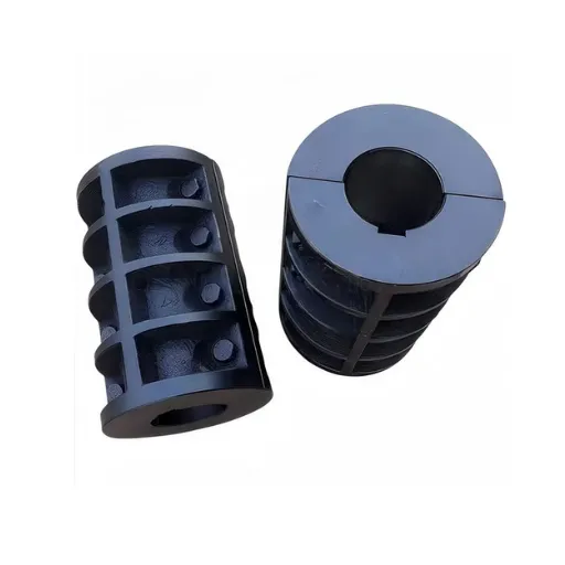
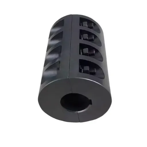
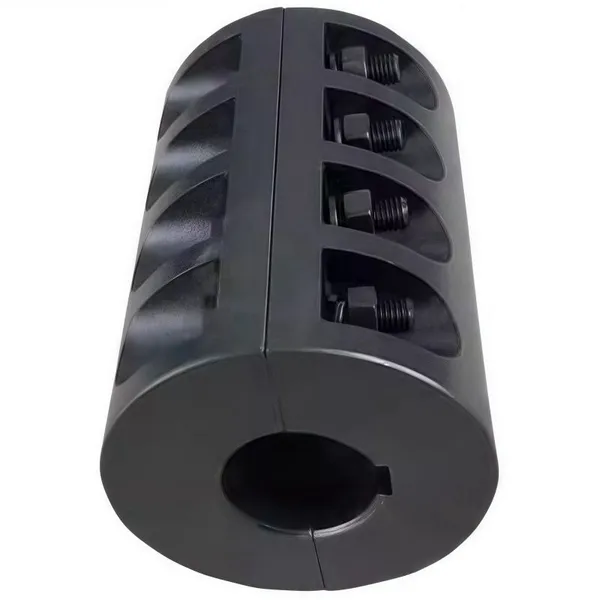
Clamp Coupling
A clamp coupling uses a split cylindrical body that clamps around the two shaft ends. It may use one or two clamp screws to create a friction grip.
Best for: Small instrumentation shafts, servo drives, and light machinery.
Advantages: Easy installation, no keyway required, good for small diameters.
Limitations: Lower torque transmission than keyed designs, sensitive to shaft surface finish.
Disc Rigid Coupling
A disc rigid coupling uses a thin metal disc bolted between two hubs. Strictly speaking, many disc couplings are flexible because the disc allows some misalignment. However, stiff disc designs with limited flex are sometimes classified as rigid couplings for precision servo applications.
Best for: High-speed precision drives and servo systems.
Advantages: Lightweight, zero backlash, balanced construction.
Limitations: Lower misalignment tolerance than true flexible disc couplings.
Custom Rigid Couplings
When catalog sizes don't fit, a custom rigid coupling can be manufactured to match specific bore sizes, flange dimensions, bolt patterns, or material requirements. This is common when replacing legacy couplings or integrating new equipment.
Hebei Suju specializes in custom rigid coupling manufacturing for non-standard rigid couplings. Send us your drawing or worn sample for an engineering review.
Which rigid coupling type fits your application? Compare the main options below.
| Type | Torque Capacity | Best For | Key Feature |
|---|---|---|---|
| Flange | Very high | Pumps, compressors, gearboxes | Bolted face-to-face hubs |
| Sleeve | Medium | Small motors, vertical pumps | Single cylindrical sleeve |
| Clamp | Low to medium | Servos, instrumentation | Split clamp body, no keyway |
| Disc | Medium | High-speed precision drives | Lightweight, balanced |
| Custom | Variable | Legacy replacement, special layouts | Made to drawing |
Rigid Coupling vs Flexible Coupling
The most important decision in coupling selection is whether the shafts are rigidly connected or allowed to move. A rigid coupling and a flexible coupling solve different problems.
A rigid coupling is the right choice when:
Shaft alignment can be maintained within tight tolerances.
Zero backlash and direct torque transmission are required.
The drive operates at high speed with minimal vibration.
The application needs the simplest, most compact connection.
A flexible coupling is the right choice when:
Thermal expansion, bearing wear, or assembly tolerances create misalignment.
Vibration damping or shock absorption is needed.
The driven machine has different thermal growth than the driver.
The application requires tolerance for occasional overload or reversing loads.
For a deeper comparison, see our guide to gear coupling vs flexible coupling. The same principles apply when comparing rigid and flexible couplings.
Can a rigid coupling replace a flexible coupling? Only if the shafts are truly aligned and remain aligned. In most industrial drives with motors, pumps, and gearboxes, some misalignment is unavoidable. Specifying a rigid coupling in those cases trades lower cost for higher bearing load and shorter machine life.
Rigid Coupling Selection: Five Key Factors
Rigid coupling selection isn't just about matching the shaft diameter. The right coupling depends on torque, speed, alignment, environment, and assembly method. For a broader approach, see our rigid coupling selection guide at coupling selection guide.
1. Rated Torque and Service Factor
Start with the nominal torque of the drive system. Because a rigid coupling transmits torque directly, it must handle the full continuous torque and any peak loads from startup, braking, or shock.
As a simple rule:
Calculate nominal torque from motor power and speed.
Multiply by a service factor based on the application (typically 1.25 to 2.5 for machinery with steady loads).
Select a coupling with a rated torque at least equal to the adjusted value.
For example, a 75 kW motor running at 1,500 RPM produces approximately 477 N·m of nominal torque. With a service factor of 1.5, the coupling should be rated for at least 716 N·m.
AGMA service factor tables help engineers match the coupling to the severity of the drive. Applying the correct AGMA service factor ensures the rigid coupling rating covers peak loads. Manufacturer catalogs also provide application-specific factors.
2. Operating Speed
Rigid couplings are suitable for high-speed applications because they have no flexible element to generate heat or imbalance. However, high-speed drives require attention to balance. An unbalanced coupling at high RPM causes vibration, bearing load, and noise. For speeds above 3,600 RPM, specify dynamic balancing to the appropriate ISO 10441 balancing grade as part of an ISO-certified manufacturing process.
At Hebei Suju, we can perform dynamic balancing on rigid couplings when the application demands it. This is especially important for high-speed pumps, compressors, and precision spindles.
3. Shaft Alignment
Rigid couplings require precise shaft alignment. Before selecting a rigid coupling, measure or confirm the expected alignment condition:
Angular misalignment: The angle between the two shaft centerlines.
Radial misalignment: The parallel offset between shaft centerlines.
Axial movement: The expected end float of the connected shafts.
A rigid coupling can tolerate only minimal values. If the expected misalignment exceeds a few hundredths of a millimeter, a flexible coupling is the safer choice.
4. Operating Environment
The environment affects material selection, sealing, and surface protection. Consider these factors:
Temperature: High temperatures can change fit tolerances and material strength.
Dust and moisture: Open designs need protection in dirty or wet environments.
Corrosion: Chemical plants and marine applications may require corrosion-resistant coatings or materials.
Safety: Some applications require guards or limited end float designs.
For outdoor or corrosive environments, specify a coated or stainless-steel rigid coupling. For clean indoor machinery, a standard carbon steel coupling with a protective oil film is usually sufficient.
5. Service Life and Maintenance Requirements
Rigid couplings can last for decades when they're properly aligned and protected. But neglect alignment, and the connected bearings will fail quickly. Before selecting a rigid coupling, consider:
How often the coupling can be inspected.
Whether the shafts can be realigned during maintenance.
Whether the coupling can be removed without moving the connected machines.
Whether the application can tolerate downtime for maintenance.
A coupling that's difficult to access should use a flanged design for easier removal. A coupling in a critical drive should be monitored for temperature and vibration.
Quick Rigid Coupling Selection Checklist
Use this checklist before finalizing a specification:
Nominal torque calculated from motor power and speed
Service factor applied for shock, reversing, or duty-cycle loads
Maximum operating speed confirmed and balancing specified if required
Expected angular, radial, and axial misalignment documented
Environmental factors reviewed (temperature, dust, moisture, chemicals)
Maintenance access and removal method planned
Flexible coupling considered if alignment cannot be guaranteed
Need help with a specific application? Request a quotation and send us your drive details.
Common Rigid Coupling Applications
These couplings appear across industry wherever shafts can be held in precise alignment. Common rigid coupling applications include pumps, compressors, gearboxes, machine tools, and precision positioning systems.
Pumps and Compressors
In mining and cement plants, large centrifugal pumps and compressors often use flange rigid couplings between motors and driven equipment. A properly aligned rigid coupling for pumps transfers torque directly without adding compliance. The shafts are aligned during commissioning and monitored during operation. Any misalignment is corrected before it damages the coupling or bearings.
Gearboxes and Transmissions
Rigid couplings connect gearboxes to output shafts in applications where the alignment is controlled by the machine structure. This rigid coupling connection preserves torsional stiffness and positioning accuracy.
Machine Tools and Precision Machinery
Lathes, mills, and grinding machines use rigid couplings or stiff disc couplings on spindle and feed drives. These applications need zero backlash and precise angular positioning.
Steel and Metallurgy
In steel and metallurgy applications, rigid couplings are used on auxiliary drives where alignment is maintained by rigid housings. Main mill drives usually require flexible or drum gear couplings to tolerate shock loads and misalignment.
Automation and Servo Systems
Clamp and disc-style rigid couplings are common in automation and servo applications where compact size, zero backlash, and fast response matter.
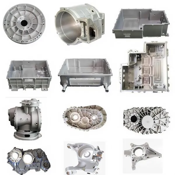
Materials and Manufacturing
The performance of a rigid coupling depends on material quality and machining accuracy. At Hebei Suju, our rigid coupling hubs and sleeves are typically manufactured from carbon steel such as 45# steel or alloy steel such as 42CrMo. For corrosive environments, we can supply stainless steel or coated carbon steel.
Key manufacturing steps include:
Forging or bar-stock preparation: Ensures grain structure and material integrity.
Rough machining: Brings the part close to final dimensions.
Heat treatment: Improves strength and hardness where required.
Finish machining: Achieves final bore, keyway, and flange tolerances.
Inspection: Dimensional checks, hardness testing, and runout verification.
Assembly and preservation: Surface protection and corrosion-resistant packing for shipment.
Our full-process quality control ensures that each step is documented and repeatable. We can provide inspection reports and material certificates on request.
At a machine tool builder in Shandong, engineer Li Wei noticed premature bearing failure on a new spindle drive. The rigid coupling had been selected correctly for torque, but the bore had been reamed 0.05 mm oversize to make assembly easier. The loose fit allowed micro-movement, fretting the shaft and coupling hub.
After replacing the coupling with a properly sized interference-fit hub and verifying shaft alignment to 0.01 mm runout, the bearing life returned to specification. The correction took one day. It saved a month of warranty claims.
Installation Best Practices
Proper rigid coupling installation is critical. Even a high-quality coupling will fail if the shafts are misaligned or the fit is wrong. Follow these guidelines:
Align shafts before installing the coupling. Do not rely on the coupling to pull the shafts into alignment.
Check runout after assembly. Rotate the shafts and measure radial and axial runout at the coupling faces. Learn how to measure shaft misalignment for step-by-step guidance.
Use the correct fit. A loose bore causes fretting; a too-tight bore makes removal difficult and can damage the shaft.
Torque bolts to specification. Uneven bolt torque causes hub distortion and runout.
Protect machined surfaces. Corrosion on the shaft or hub bore can change the fit.
For critical applications, schedule rigid coupling inspection during planned maintenance shutdowns. Early detection of fretting, bolt loosening, or alignment drift prevents unexpected failures.
Storage and Handling
Store spare couplings and components in a clean, dry location. Keep them off the floor. Protect machined surfaces from corrosion. Handle finished couplings carefully to avoid impact damage to bores or flange faces.
Common Failure Modes
Even a correctly selected rigid coupling can fail if operating conditions change. Recognizing the early signs saves the connected equipment.
Misalignment Overload
Rigid couplings tolerate almost no misalignment. Running with even small angular or radial error concentrates load on one side of the coupling and transfers force into the bearings. The result is fretting, bolt fatigue, and bearing wear.
Improper Fit
A bore that is too loose allows movement between the shaft and hub. The resulting fretting damages both the shaft and the coupling. A bore that is too tight can crack the hub during assembly.
Bolt Loosening
Vibration and thermal cycling can loosen coupling bolts over time. Loose bolts create impact loads and misalignment. Regular torque checks prevent this.
Overload and Fatigue
Repeated shock loads above the coupling's rating cause fatigue cracks. Matching peak torque to the coupling rating prevents fatigue failures.
Corrosion
Moisture and process chemicals attack the shaft-to-hub interface and bolt threads. Protective coatings and regular inspection extend service life.
When to Consider a Custom Rigid Coupling
Catalog couplings fit many applications, but some situations require a custom design. Read about custom couplings from drawing to delivery to see how Hebei Suju handles non-standard orders. Consider a custom rigid coupling when:
The shaft bores are non-standard sizes.
The flange bolt pattern must match legacy equipment.
The torque or speed falls outside standard catalog ranges.
The coupling must fit in a confined space.
The environment requires special materials or coatings.
At Hebei Suju, we specialize in custom rigid coupling manufacturing. Send us your drawing or a worn sample, and our engineers will review manufacturability, recommend materials, and provide a quotation.
Frequently Asked Questions
Here are answers to common questions about rigid couplings.
What is it used for?
A rigid coupling connects two aligned rotating shafts so they rotate as a single unit. It is used where precise alignment can be maintained and where zero backlash and direct torque transmission are required.
What are the main types of rigid couplings?
The main rigid coupling types are flange, sleeve, clamp, and disc rigid couplings. Flange couplings handle the highest torque. Sleeve and clamp couplings are more compact. Disc couplings are used for precision high-speed drives.
How do I select one?
Start with rigid coupling selection basics: torque and service factor. Then check operating speed, required alignment accuracy, environment, and maintenance access. If alignment cannot be guaranteed, consider a flexible coupling instead.
When should it be replaced?
Replace the coupling when inspection shows fretting, bolt loosening, flange cracking, or damage to the bore. Preventive replacement during planned shutdowns avoids emergency failures.
What is the difference between a rigid coupling and a flexible coupling?
A rigid coupling connects shafts with no allowance for misalignment. A flexible coupling accommodates angular, radial, and axial movement. Rigid couplings are simpler and more compact; flexible couplings protect bearings and dampen vibration.
Can it handle misalignment?
No. A rigid coupling cannot compensate for misalignment. The shafts must be aligned within tight tolerances during installation and must remain aligned during operation.
What does rigid coupling installation involve?
Rigid coupling installation involves aligning the shafts, checking bore fit, mounting the hubs, bolting the flanges or tightening the clamp, and verifying runout. Proper alignment is the most critical step.
Conclusion
A rigid coupling is a simple but demanding component. When the shafts are aligned and stay aligned, it delivers reliable, zero-backlash power transmission with minimal maintenance. When alignment is uncertain, a rigid coupling can cause expensive damage to bearings, seals, and driven equipment.
To select the right rigid coupling, start with torque and service factor. Then check speed, alignment accuracy, environment, and maintenance access. Match the coupling type to the application priority. When a catalog part doesn't fit, a custom design from an experienced manufacturer keeps the project moving.
Hebei Suju is a custom rigid coupling manufacturer with a full range of industrial couplings, including rigid, flexible, and gear coupling designs for pumps, compressors, gearboxes, machine tools, and precision drives. Whether you need a standard flange coupling or a custom solution for a difficult application, we can help.
Recently Posted
-
Diaphragm Coupling: A High-Speed, Zero-Backlash Solution
July 3, 2026A single degree of angular misalignment at 10,000 RPM can destroy a precision drive in months. For high-speed compressors, turbine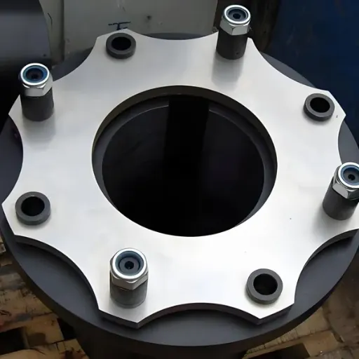 Read More
 -
Drum Gear Coupling: Selection, Types, and Industrial Applications
July 3, 2026A maintenance manager at a cement plant in Indonesia once told me his team had replaced the same coupling three times in two years Read More
 -
Gear Coupling: Types, Selection, and Uses
July 3, 2026At a steel rolling mill in Turkey, a main drive coupling failed during the night shift. The maintenance team replaced it with an o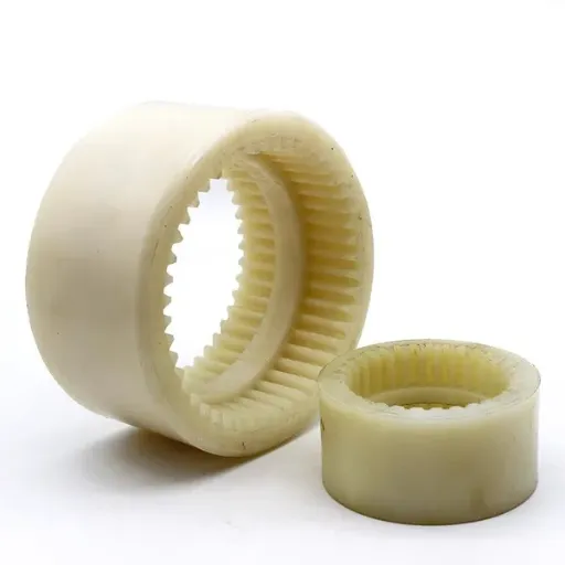 Read More
 -
Flexible Coupling: Types, Selection, and Uses
July 3, 2026At a water treatment plant outside São Paulo, a vertical turbine pump began rattling every time it started. The maintenance team c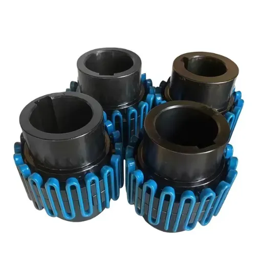 Read More

Contact Us

Recommended Products
-
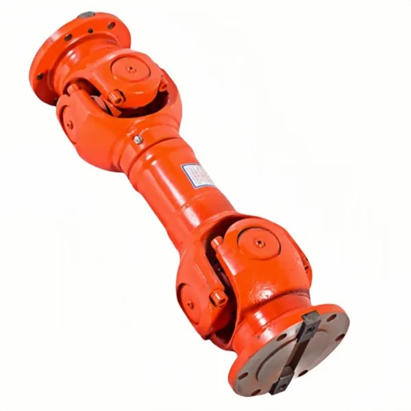
 OEM Customizable Cardan Shaft Coupling Flexible Rigid Steel for Air Compressor Propeller Universal Construction Printing ShopsNegotiableMOQ: 2 Pieces
 -
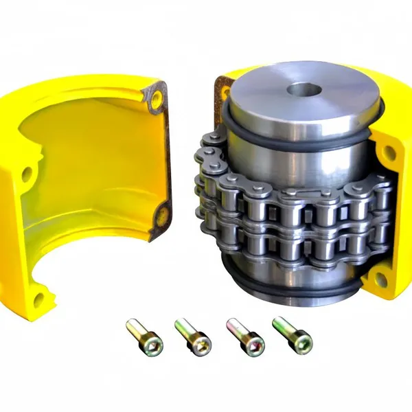
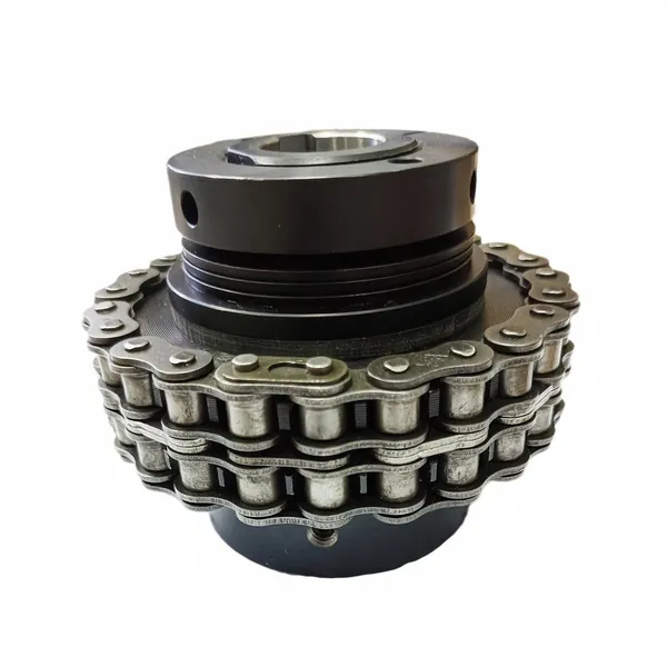
Kc Coulpling Roller Chain Coupling Set With Chain and Sprocket for General MachineryNegotiableMOQ: 1 Piece
-
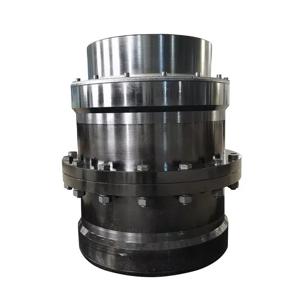
High Transmission Efficiency Drum Gear Coupling Easy Installation Gear Coupler For Heavy MachineryNegotiableMOQ: 10 Pieces
-
OEM Customized Precision Cast Iron Zinc Aluminum Die Castings New Hydraulic Parts Fittings 1 Year WarrantyNegotiableMOQ: 100 Pieces
-
High-Torque Roller Chain Coupling Durable Steel Aluminium Construction Customizable Precision Engineering OEM Shaft CouplingsNegotiableMOQ: 2 Pieces
-
Customizable Rigid Iron Steel Aluminium Rubber Tyre Coupling OEM Support for Pumps Industrial Equipment Construction IndustriesNegotiableMOQ: 10 Pieces
-
High Torque JQ/JQW Type Clamp Coupling for Motor & Gearbox 45 Steel Jacketed Iron Disc Structure Flexible Rigid OEM SupportedNegotiableMOQ: 2 Pieces
-
Jsb Flexible Grid Coupling With Metallic Elastic Element Factory Direct Spider Snake Spring CouplingNegotiableMOQ: 10 Pieces
-
Heavy Duty Universal Coupling High Quality Universal Shaft for Machinery and EquipmentNegotiableMOQ: 1 Piece
-
Heavy Duty Js Series Snake Spring Grid Coupling, Large Torque Conveyor ShaftNegotiableMOQ: 10 Pieces
-
Yl Series Rigid Flange Coupling Power Transmission PartsNegotiableMOQ: 2 Pieces
-
Flange Coupling for Water Pump and Compressor Applications With Rubber Gasket SealNegotiableMOQ: 2 Pieces
-
Flexible Universal Shaft Flange Coupling for Marine and Industrial Drive SystemsNegotiableMOQ: 10 Pieces
-
High Quality Yl Type Rigid Flange Coupling Mechanical Transmission CouplingNegotiableMOQ: 2 Pieces
-
Stainless Steel Flexible Universal Joint Coupling for Motor Flange Gear Pump and Spline ShaftNegotiableMOQ: 1 Piece
-
Compact Drum Gear Coupling for Heavy Industrial Transmission High Torque CapacityNegotiableMOQ: 10 Pieces
-
Standard or Customized Jaw Beam (Helical) Flexible Coupling for General MachineryNegotiableMOQ: 10 Pieces
-
TL Series Elastic Pin Coupling Easy Replace Rubber Bush Coupling With Shaft Misalignment CompensationNegotiableMOQ: 10 Pieces
-
Cost Effective TL Elastic Pin Coupling Flexible Buffer Coupler For Light Duty Industrial EquipmentNegotiableMOQ: 10 Pieces
-
Professional Manufacture SWC-Wf Cardan Shaft Universal Joint CouplingNegotiableMOQ: 1 Piece