
 Business License
Curved Tooth Coupling: How Crowned Teeth Carry Torque and Misalignment
On a humid Monday in July, a paper mill engineer named Sofia pulled a failed gear coupling off a stock pump drive and saw the same pattern for the third time that year. The teeth were not worn across their faces. They were chewed at the tips, right where angular misalignment from thermal growth had forced all the load onto a narrow edge. The coupling was rated for the torque, but its straight teeth had nowhere to go when the shafts moved. Her question stopped being about torque and started being about geometry: would a curved tooth coupling spread that contact and end the cycle?
If you have ever replaced a gear coupling that failed at the tooth tips instead of across the face, you already understand the problem the curved tooth coupling was built to solve. It uses a crowned, barrel-shaped external tooth profile so the hub can rock inside the sleeve while keeping contact distributed along the tooth. That single geometric choice is why a curved tooth coupling tolerates misalignment that would destroy a straight-tooth design, and why it underlies the heavy-duty drum gear coupling series used across steel, mining, and paper.
In this guide, you will learn what a curved tooth coupling is, how the crowned profile works, where it outperforms straight-tooth and elastomer designs, and how to select the right size for your drive. We will also cover the manufacturing details that make the profile accurate, plus when a catalog part is not enough.
What Is a Curved Tooth Coupling?
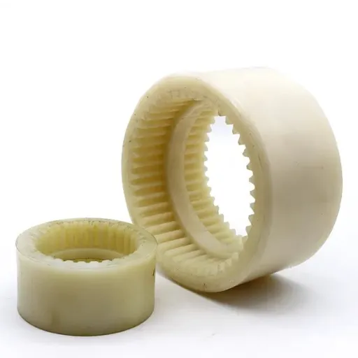
A curved tooth coupling is a gear coupling whose external hub teeth are crowned along their length, so each tooth is slightly barrel-shaped rather than straight. The internal sleeve teeth stay straight. When the two shafts sit at a small angle, the crowned hub tooth rolls across the straight sleeve tooth instead of digging into its edge, which keeps torque flowing through a broad contact zone.
The design is built around four main parts:
Two external curved-tooth hubs that mount to the shafts
Two internal straight-tooth sleeves that connect the hubs
Seals and fasteners that retain lubricant and exclude dust
A spacer option on double-engagement versions for long shaft gaps
The crown radius is the key geometric feature. A smaller crown radius permits more angular misalignment but concentrates contact; a larger radius spreads contact but tolerates less angle. The manufacturer balances the two for the application. This is why the curved tooth coupling is the working principle behind the GIICL drum gear coupling and the brake-equipped NGCL series: both rely on the same crowned-tooth geometry.
At Hebei Suju, we machine curved tooth couplings from forged alloy steel, heat-treat the teeth, and verify the crown profile before assembly. Each coupling arrives ready to carry torque and absorb misalignment.
Replacing a coupling that failed at the tooth tips? Send our engineers your drive data and we will confirm whether a curved tooth profile is the fix before you order.
How the Curved Tooth Profile Works
The whole value of a curved tooth coupling lives in the contact pattern. In a straight-tooth gear coupling, the hub and sleeve teeth meet along their full width only when the shafts are perfectly aligned. Introduce a small angle and the contact collapses to the tooth edges, so stress spikes and wear accelerates. The crowned profile changes that behavior completely.
Three things happen when the teeth are curved:
Contact stays centered. As the hub rocks, the crown keeps the contact zone near the middle of the tooth face instead of the edge.
Load distributes across teeth. More teeth share the torque at any moment, which lowers peak stress on any single tooth.
Misalignment becomes motion, not damage. Angular, radial, and axial movement turn into a rolling action rather than a scraping one.
The trade-off is that the curved tooth coupling needs lubrication. The teeth slide slightly against each other as they flex, and without grease or oil the contact zone wears. With the right lubricant and a sealed sleeve, the same contact that would destroy a dry coupling becomes a controlled, long-lived interface.
This is also why crown accuracy matters more than almost any other dimension. A crown that is too flat behaves like a straight tooth and edge-loads. A crown that is too steep concentrates contact in a narrow band. The profile has to match the rated misalignment, which is a manufacturing question as much as a design one.
Curved Tooth Coupling vs Other Designs
Choosing a curved tooth coupling is really choosing a balance of torque, misalignment, and maintenance. The table below compares it with the two most common alternatives.
| Design | Torque Capacity | Misalignment Tolerance | Lubrication | Typical Use |
|---|---|---|---|---|
| Curved tooth gear coupling | Very high | High (angular, radial, axial) | Required | Steel mills, paper, pumps, fans |
| Straight-tooth gear coupling | Very high | Low | Required | Near-perfect alignment only |
| Elastomer jaw/tyre coupling | Low to medium | Medium | Not required | General machinery, light drives |
A straight-tooth gear coupling can match the torque of a curved tooth coupling on paper, but only when alignment is near perfect, which field equipment rarely delivers. An elastomer coupling needs no lubrication and installs quickly, but it cannot carry the same torque and the insert degrades with heat and chemicals. The curved tooth coupling sits between them: high torque, real misalignment tolerance, and a lubrication requirement that is easy to manage with a sealed design.
For a side-by-side of elastomer options, our flexible coupling types guide covers the lower-torque end of the range.
Where Curved Tooth Couplings Are Used
The curved tooth coupling earns its place wherever torque is high and the shafts refuse to stay perfectly aligned. Four industries account for most of the demand.
Steel and Metallurgy
Rolling mills and continuous casters push enormous torque through drives that flex under load. A curved tooth coupling absorbs the angular change from roll adjustments and bite shocks without edge-loading the teeth. It is the default choice for work-roll and intermediate drives, and our steel and metallurgy applications work reflects that pattern.
Paper and Pulp
Dryer sections, calendars, and stock pumps run hot and long, and thermal growth moves the shafts. This was exactly Sofia's problem from the opening. Switching her stock pump drive to a correctly crowned curved tooth coupling moved the contact off the tooth tips and back onto the face, and the replacement has run through two maintenance cycles without the tip wear that defined the old failures.
Mining and Cement
Crushers, mills, and kilns operate in dust and under shock. A sealed curved tooth coupling keeps lubricant in and grit out while the crown tolerates the misalignment that heavy foundations develop. The same principle drives our mining and cement applications, where contamination control matters as much as torque.
Pumps, Fans, and Marine Drives
Not every curved tooth coupling works in a mill. Smaller sizes connect motors to large pumps, induced-draft fans, and marine auxiliary drives. In these drives, the crowned teeth protect bearings from the small but constant misalignment that builds over years of operation.
How to Select a Curved Tooth Coupling
Selecting a curved tooth coupling comes down to six factors: torque, speed, misalignment, bore, crown profile, and environment. Get any one of them wrong and the coupling won't last.
1. Calculate the Required Torque
Start with the motor power and operating speed, then apply a service factor. A steady pump might use a service factor near 1.5. A reversing mill with heavy shock can demand 2.5 or higher. Standards such as AGMA publish service factor guidance for common applications.
The simple method works like this:
Calculate nominal torque from power and speed.
Multiply by the application service factor.
Select a curved tooth coupling whose rated torque meets or exceeds the result.
2. Confirm the Operating Speed
Curved tooth couplings handle a wide speed range, but high-speed drives need attention to balance. Above roughly 3,000 RPM, specify dynamic balancing to the appropriate ISO grade. An unbalanced curved tooth coupling at speed creates vibration, bearing load, and noise that shorten the life of the whole drive train.
3. Estimate the Misalignment
Measure or estimate the angular, radial, and axial misalignment the coupling will see, including thermal growth. Select a size whose allowable values exceed your estimate with margin. If the layout needs axial movement for maintenance, a spacer-type curved tooth coupling lets you remove the center section without moving the connected machines.
4. Match the Bore and Keyway
The hub bore must fit the shaft with the correct interference or clearance. Provide the shaft diameter, keyway size, and tolerance. If your shaft is non-standard, a custom bore is often the simplest solution.
5. Specify the Crown for the Application
This is the step most buyers skip. Tell the manufacturer the expected angular misalignment so they can match the crown radius. A drive with large thermal movement needs a more generous crown; a high-speed, well-aligned drive benefits from a flatter crown that spreads contact. The crown is not a detail; it is the design.
6. Account for the Environment
Temperature, dust, moisture, and chemicals affect material, seals, and lubricant. For outdoor or dusty service, specify a sealed curved tooth coupling. For corrosive atmospheres, discuss coating or material options with the manufacturer.
For a step-by-step walkthrough of the torque and misalignment side, our coupling selection guide covers the process in more detail.
Manufacturing Quality: Why Tooth Geometry Decides Service Life
Two curved tooth couplings can look identical on a drawing and perform very differently in service. The difference is in how accurately the crown is cut and how consistently the teeth are hardened.
A reliable curved tooth coupling starts with forged alloy steel such as 42CrMo or an equivalent grade. Forging refines the grain structure and gives the teeth the toughness they need to resist shock. After rough machining, the crown is generated by hobbing or shaping with the correct barrel radius, then the teeth are induction hardened or carburized to a specified surface hardness and finish-machined to final tolerance.
The steps that matter most include:
Incoming material inspection with traceability to the heat number
Controlled crown generation verified by profile measurement
Controlled heat treatment verified by hardness testing
Finish machining of bores, keyways, and tooth profiles
Contact-pattern inspection to confirm the crown centers the load
Optional dynamic balancing for high-speed drives
At Hebei Suju, our full-process quality control covers every stage from raw material to final packing. We provide material certificates and inspection reports on request, and our ISO certifications support supplier qualification for OEM and MRO buyers.
Want a sizing walkthrough before you commit? Our gear coupling selection guide for heavy machinery covers torque, service factors, and misalignment in detail.
Common Failure Modes and How to Avoid Them
Most curved tooth coupling failures trace back to a short list of causes. Knowing them helps you specify a coupling that lasts.
Edge Loading from Excess Misalignment
A curved tooth coupling tolerates misalignment, but operating beyond the rated angle pushes contact back to the tooth tips and recreates the very failure the crown was meant to prevent. If the shafts cannot be aligned within the rated values, choose a larger size or a spacer design.
Tip Wear from an Incorrect Crown
A cement plant once ran a replacement coupling whose crown was cut too flat for the drive's thermal movement. Within a season the teeth wore at the tips, almost as if it were a straight-tooth part. After the crown was re-cut to the correct radius for the measured misalignment, the next coupling ran for years. The crown has to match the application, not just the size number.
Tooth Wear from Poor Lubrication
The curved profile still slides slightly as it flexes, so lubricant is part of the design. Starved teeth wear fast, and the wrong grease can separate under centrifugal load. Follow the recommended lubricant and interval.
Contamination from Failed Seals
Dust and moisture entering the mesh accelerate wear dramatically. Inspect seals during planned maintenance and replace them before they fail.
Loosening from Improper Fit or Bolt Torque
A hub that is loose on the shaft, or bolts that are not torqued evenly, causes runout and vibration. Follow the installation procedure and verify the fit.
If a coupling has already failed, don't simply reorder the same part. Investigate the root cause first. The replacement must solve the problem that caused the failure, or it will fail the same way.
When to Order a Custom Curved Tooth Coupling
Catalog curved tooth couplings cover many applications, but some situations call for a custom build. Consider a custom curved tooth coupling when:
The shaft bores are non-standard sizes.
The expected misalignment requires a specific crown radius.
The space between shafts requires a special spacer length.
The torque or speed falls outside standard catalog ranges.
The coupling must match a legacy part that is no longer available.
The environment requires special materials, seals, or coatings.
A custom coupling supplier should review your drawing or worn sample, confirm manufacturability, recommend the crown profile and material, and provide a clear quotation with lead time. At Hebei Suju, we regularly reverse-engineer worn curved tooth couplings for paper mills, steel plants, and marine drives through our custom coupling manufacturing service. Sofia, the engineer from the opening, shipped her worn sample on a Wednesday and had a confirmed replacement design, with the crown radius matched to her measured thermal movement, by Friday. The new curved tooth coupling arrived inside her shutdown window, and the tip-wear cycle ended.
That outcome is why a manufacturing partner matters more than a price list. When the coupling lives or dies on tooth geometry, you want a supplier who controls the crown machining, heat treatment, and contact-pattern inspection under one roof.
Frequently Asked Questions
What is a curved tooth coupling?
A curved tooth coupling is a gear coupling whose external hub teeth are crowned along their length, so each tooth is slightly barrel-shaped. The crowned profile lets the hub rock inside the straight-tooth sleeve while keeping contact distributed, which allows angular, radial, and axial misalignment under high torque.
Is a curved tooth design the same as a drum gear coupling?
They describe the same geometry from two angles. "Curved tooth coupling" names the crowned tooth profile, while "drum gear coupling" is the common product name for couplings built on that profile, including the GIICL and NGCL series. In practice, a drum gear coupling is a curved tooth coupling.
How does the crowned tooth profile handle misalignment?
The crown keeps the contact zone near the center of the tooth face as the hub rocks, instead of letting it collapse to the edge. Misalignment becomes a rolling action rather than edge contact, which lowers stress and wear.
Does a curved tooth coupling need lubrication?
Yes. The teeth slide slightly as they flex, so grease or oil is required to protect the contact zone. A sealed design with the right lubricant, replenished on schedule, delivers long service life.
Can a curved tooth coupling run at high speed?
Yes, but high-speed drives require dynamic balancing and proper lubrication. Above roughly 3,000 RPM, specify balancing to the appropriate ISO grade and confirm the maximum rated speed with the manufacturer.
Can you manufacture a curved tooth coupling from a worn sample?
Yes. A manufacturer with reverse-engineering capability can measure a worn sample, confirm the dimensions, material, and crown profile, and produce a matching replacement. This is common for legacy equipment where the original part is discontinued.
Conclusion
The curved tooth coupling is a proven solution for high-torque drives where the shafts will not stay perfectly aligned. Selecting the right one means sizing to the adjusted torque, confirming the speed and misalignment, matching the bore, specifying the crown for the application, and accounting for the environment. Just as important, the coupling has to be built from sound material, with the crown cut accurately, hardened correctly, and inspected for contact pattern before it ships.
When you evaluate a curved tooth coupling supplier, look past the catalog. Ask about crown generation, hardness verification, contact-pattern inspection, and custom capability. A factory-direct manufacturer can answer those questions precisely and stand behind the part.
At Hebei Suju, we manufacture standard and custom curved tooth couplings for machinery manufacturers, paper mills, steel plants, mining operations, and marine drives worldwide. From catalog sizes to reverse-engineered replacements, we build couplings whose tooth geometry matches your equipment and your schedule.
Recently Posted
-
Jaw Coupling Spider Replacement: A Step-by-Step Maintenance Guide
July 28, 2026A maintenance technician at a packaging plant in Brazil noticed vibration on a motor-pump set during his morning rounds. The motor Read More
 -
Flexible Coupling for Motor Pump Sets: A Selection Guide
July 28, 2026A maintenance manager at a water treatment plant in Southeast Asia called us after replacing motor pump couplings three times in 1 Read More
 -
Flexible Shaft Coupling: Selection Guide for Industrial Drives
July 28, 2026When two rotating shafts are connected directly, even a small amount of misalignment can generate vibration, bearing load, and pre Read More
 -
Elastic Coupling: Vibration Control for Industrial Drives
July 28, 2026When a motor-pump set starts vibrating above acceptable limits, the first checks usually fall on bearing wear, impeller balance, o Read More

Contact Us

Recommended Products
-
 OEM Customizable Cardan Shaft Coupling Flexible Rigid Steel for Air Compressor Propeller Universal Construction Printing ShopsNegotiableMOQ: 2 Pieces
 -
Kc Coulpling Roller Chain Coupling Set With Chain and Sprocket for General MachineryNegotiableMOQ: 1 Piece
-
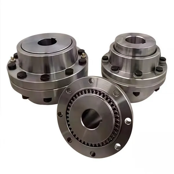
High Transmission Efficiency Drum Gear Coupling Easy Installation Gear Coupler For Heavy MachineryNegotiableMOQ: 10 Pieces
-
High-Torque Roller Chain Coupling Durable Steel Aluminium Construction Customizable Precision Engineering OEM Shaft CouplingsNegotiableMOQ: 2 Pieces
-
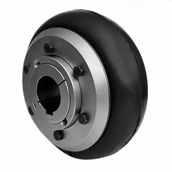
Customizable Rigid Iron Steel Aluminium Rubber Tyre Coupling OEM Support for Pumps Industrial Equipment Construction IndustriesNegotiableMOQ: 10 Pieces
-
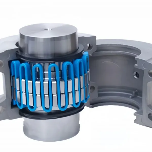
Jsb Flexible Grid Coupling With Metallic Elastic Element Factory Direct Spider Snake Spring CouplingNegotiableMOQ: 10 Pieces
-
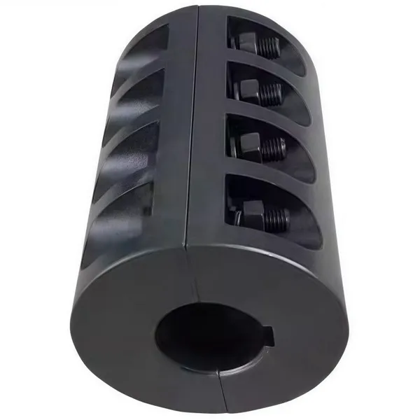
High Torque JQ/JQW Type Clamp Coupling for Motor & Gearbox 45 Steel Jacketed Iron Disc Structure Flexible Rigid OEM SupportedNegotiableMOQ: 2 Pieces
-
SWC Series Flange Universal Joint Coupling Hardened Cross Shaft Heavy Duty TransmissionNegotiableMOQ: 1 Piece
-
Heavy Duty Universal Coupling High Quality Universal Shaft for Machinery and EquipmentNegotiableMOQ: 1 Piece
-
OEM Customized Precision Cast Iron Zinc Aluminum Die Castings New Hydraulic Parts Fittings 1 Year WarrantyNegotiableMOQ: 100 Pieces
-
Yl Series Rigid Flange Coupling Power Transmission PartsNegotiableMOQ: 2 Pieces
-
Flange Coupling for Water Pump and Compressor Applications With Rubber Gasket SealNegotiableMOQ: 2 Pieces
-
Heavy-Duty Telescopic Welding Cardan Shaft for Universal UseNegotiableMOQ: 1 Piece
-
Flexible Universal Shaft Flange Coupling for Marine and Industrial Drive SystemsNegotiableMOQ: 10 Pieces
-
Durable Expansion Sleeve, Locking Assembly & Taper Lock Bushing for Robotic Arm JointsNegotiableMOQ: 1 Piece
-
High Quality Yl Type Rigid Flange Coupling Mechanical Transmission CouplingNegotiableMOQ: 2 Pieces
-
Stainless Steel Flexible Universal Joint Coupling for Motor Flange Gear Pump and Spline ShaftNegotiableMOQ: 1 Piece
-
Compact Drum Gear Coupling for Heavy Industrial Transmission High Torque CapacityNegotiableMOQ: 10 Pieces
-
Standard or Customized Jaw Beam (Helical) Flexible Coupling for General MachineryNegotiableMOQ: 10 Pieces
-
TL Series Elastic Pin Coupling Easy Replace Rubber Bush Coupling With Shaft Misalignment CompensationNegotiableMOQ: 10 Pieces